


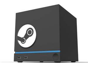
STEAM MACHINE Iota
Greetings everyone, and welcome back!
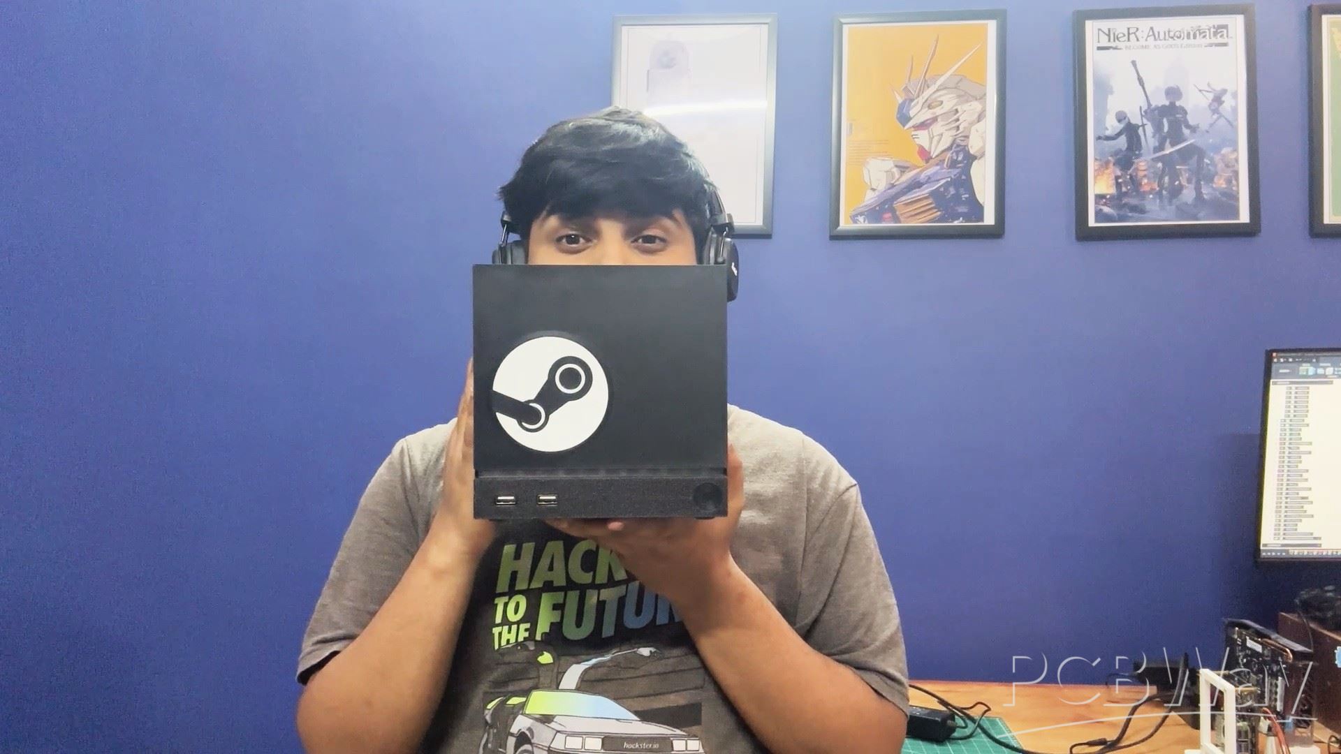

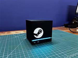
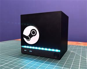
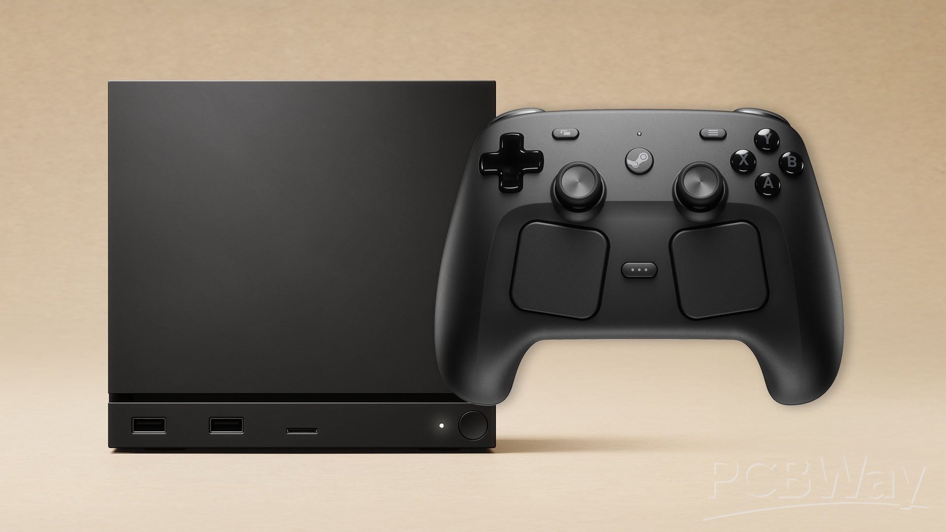
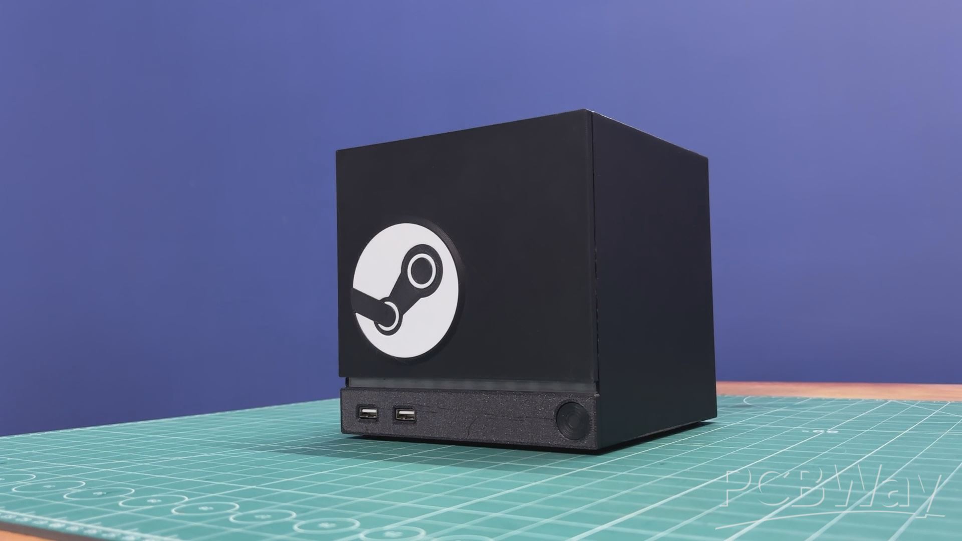
Meet my version of the new Steam Machine.
The build was inspired by the new Steam Machine that was supposed to launch, but got delayed due to the RAM crisis. I was actually planning to get one, but since I couldn’t, I decided to take matters into my own hands and build one from scratch.
I’ve worked on a few Steam Machine–style projects using SBCs, so I already had a solid starting point.
https://www.hackster.io/Arnov_Sharma_makes/bazzite-on-lattepanda-mu-setting-up-guide-4c93b4
https://www.hackster.io/Arnov_Sharma_makes/parallel-pc-wood-edition-d046ea
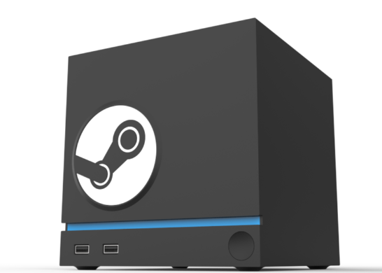
This time, I wanted to get as close as possible to the original design. After doing some research, I designed my own enclosure in Fusion 360, keeping the features and aesthetics as true to the official Steam Machine as possible.
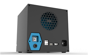
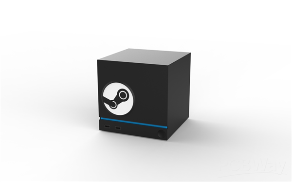
On the front, I’ve added two fully functional USB ports, an LED light bar that plays custom animations, and even a magnetic front cover that can be easily detached and swapped with different designs.
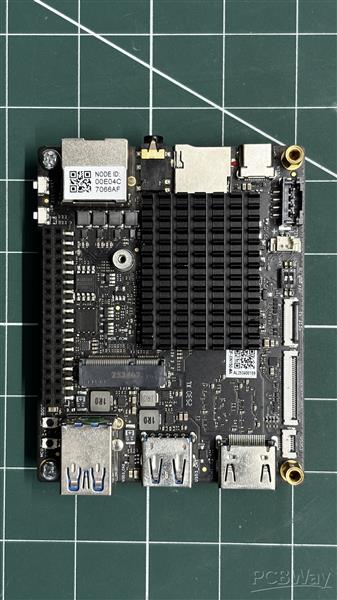
At the heart of this build is the LattePanda IOTA, featuring an Intel N150 quad-core processor, paired with a 256GB NVMe Gen 3 SSD and 16GB of DDR5 RAM. For the operating system, I’m using Bazzite, which is a Linux distro built specifically for gaming, and it runs Steam on it.
Since this system uses an x86 Intel processor, games run seamlessly thanks to Proton. In a previous project using a Raspberry Pi, I had to rely on Box86 to translate ARM architecture for gaming, which added complexity. Here, with native x86 support, the experience is far more straightforward and efficient.
In this Article, I’ll walk you through the complete build process of this Steam Machine, so let’s get started.
MATERIALS REQUIRED
These were the components used in this build:
- Lattepanda IOTA SBC
- Custom PCBs (provided by PCBWAY)
- 3D Printed Parts
- 18650 3.7V Lithium Ion cell
- WS2812B LEDs
- M2 screws
- M2 PCB Standoffs
- USB Port
- Push Switch 12x12
- 100nf Capacitor
- Header Pins
- 1W 4Ohms Speaker
- CON2 JST connector
- Connecting wires
- Heatsink for IOTA
- PCIE to M.2 HAT for IOTA
- UPS Board for IOTA
- Mechanical Switch
- DC Barrel jack
STEAM MACHINE
For the lore or background of Valve’s Steam Machine, we need to go back in time to around 2012, when Microsoft launched Windows 8. It was not a great OS, but it introduced a centralized app store ecosystem. This wasn’t a big deal for most people, but it was a huge concern for Valve, as it directly affected their entire business model.
In response, Valve announced SteamOS in 2013, a Linux-based operating system focused on gaming and open platforms. Alongside it, Valve introduced the concept of Steam Machines, PCs designed to run SteamOS in the living room, just like a console. They were meant to be smaller than traditional PCs, similar to consoles, but with the power of a PC.
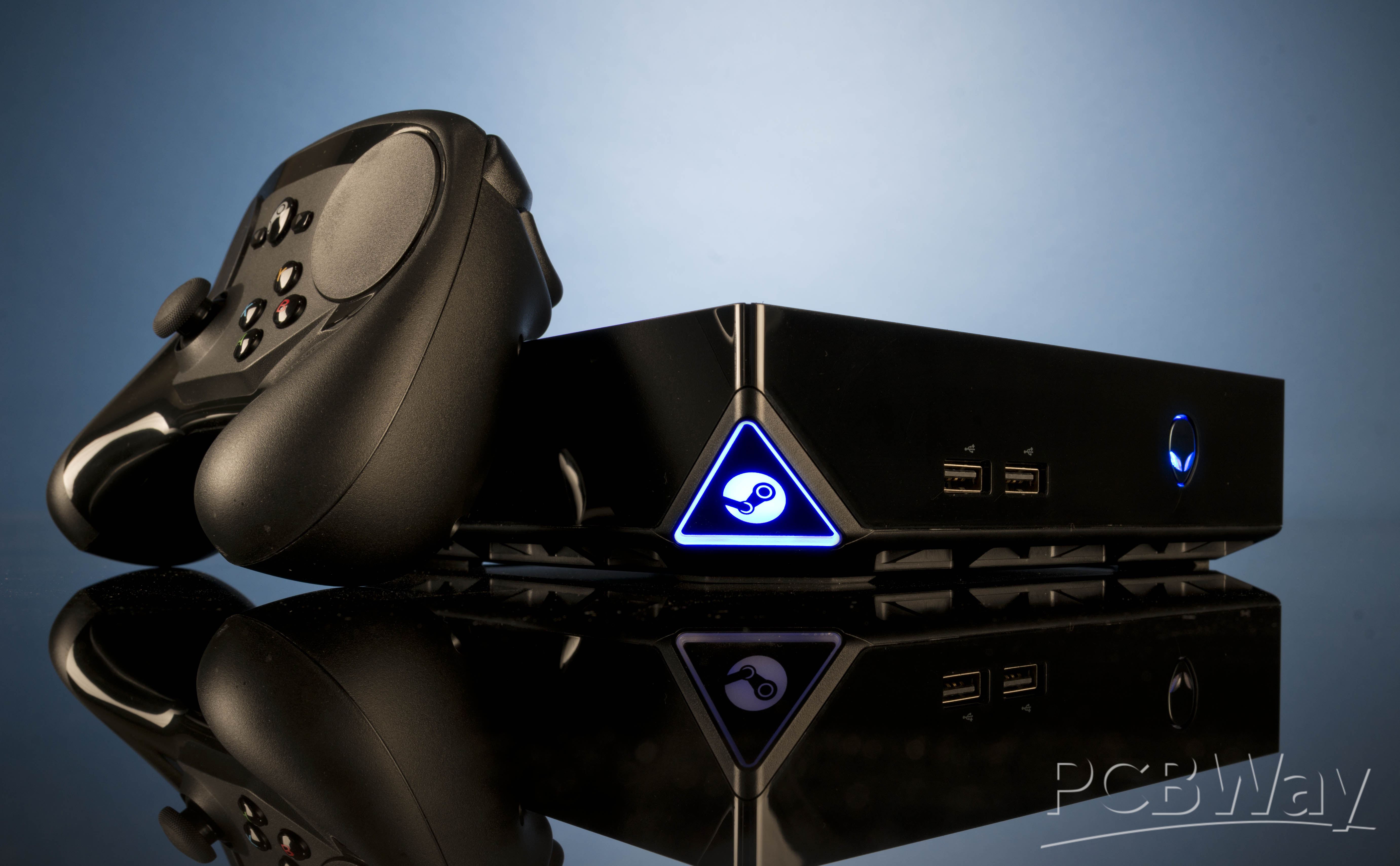
Instead of making the hardware themselves, Valve decided to partner with OEMs like Alienware, ASUS, Xi3, and many more.
During the launch of SteamOS, it was not fully ready, which led to delays and inconsistencies. Many Steam Machines shipped with Windows instead of SteamOS, defeating the original goal of the platform.
Another major issue was the lack of native Linux game support at the time. Steam Machines officially launched around 2015, but saw poor sales and low developer support, which led Valve to quietly discontinue the entire project after a few years.
In 2022, Valve launched the Steam Deck, which was truly a game-changer. It ran a refined version of SteamOS, and the key breakthrough was Proton, which is a tool developed by Valve that allows Windows games to run seamlessly on Linux. Another advantage was that Valve built the hardware in-house, giving them complete control over the development process instead of relying on OEM partners.
In late 2025, Valve announced a new generation of Steam Machines along with other hardware, including a new Steam Controller and a VR headset. It is expected to be powered by an AMD Zen 4 CPU with an RDNA3 GPU.
The launch was planned for 2026, but it has been delayed due to global RAM shortages. I was actually planning to get one, but for now, all I can do is wait.
Still, the new Steam Machine looks very promising, and if it succeeds, it could give console companies some serious competition.
NEW STEAM MACHINE
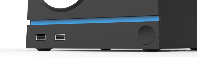
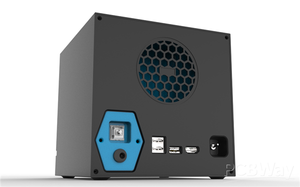
This project started with researching the design of the Steam Machine by looking at photos of the device. There was a great article and a video by PC Gamer, where they showed the internals of the Steam Machine, including detailed images of the front and back side, which were more than enough to get started with the model.
MY DESIGN
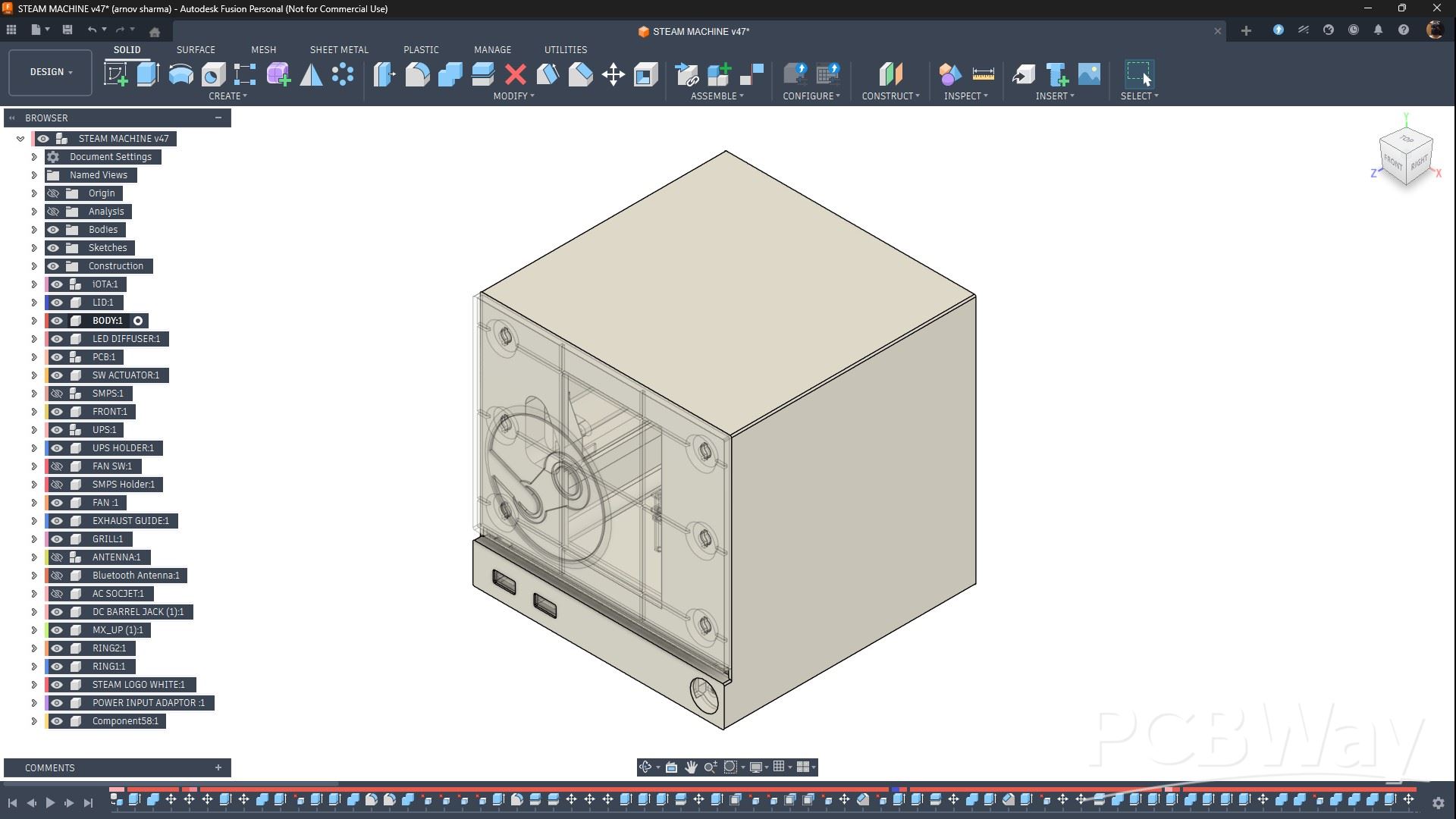
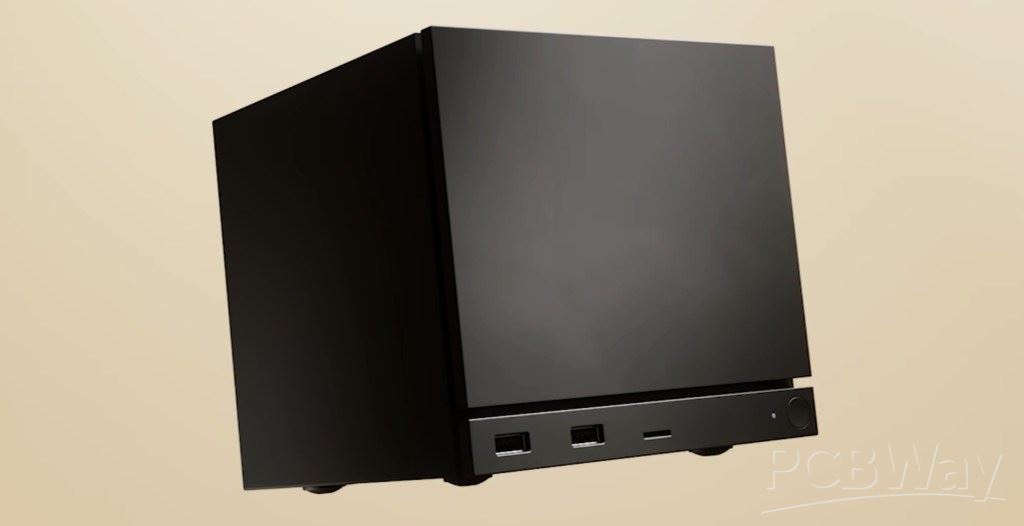
In Fusion 360, I created a box-like enclosure, mainly made up of two parts: the main body and the lid.
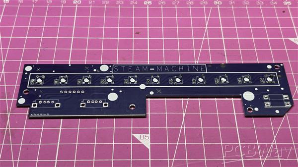
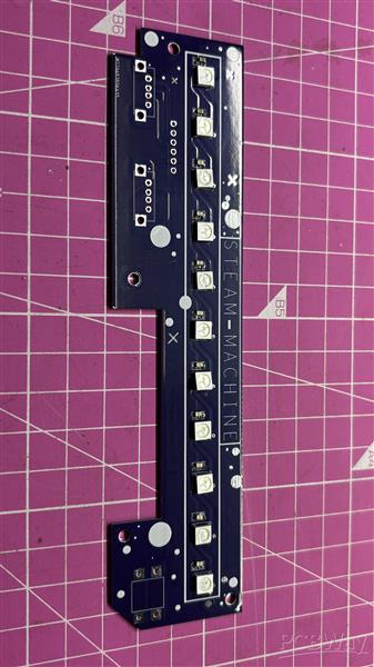
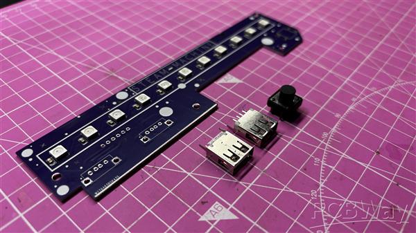
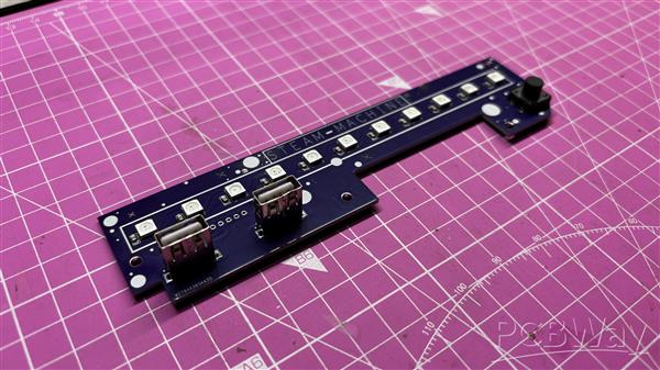
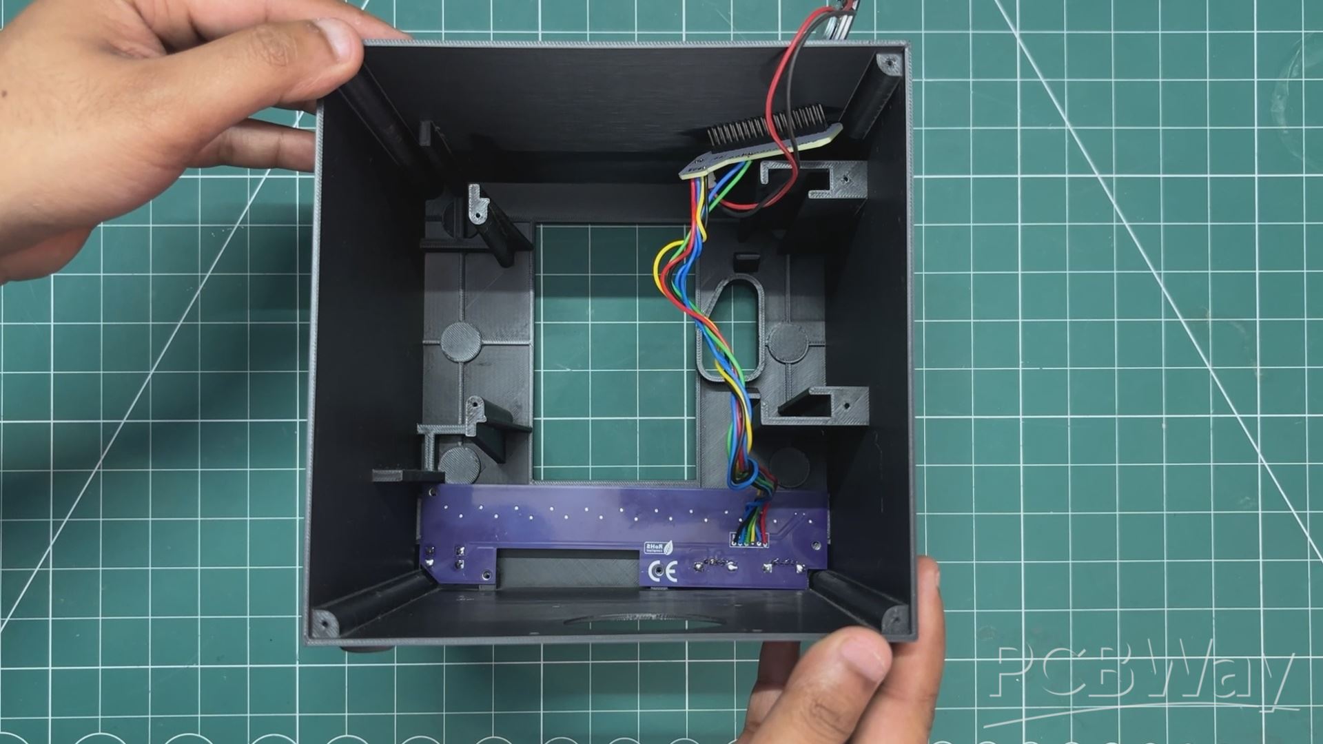
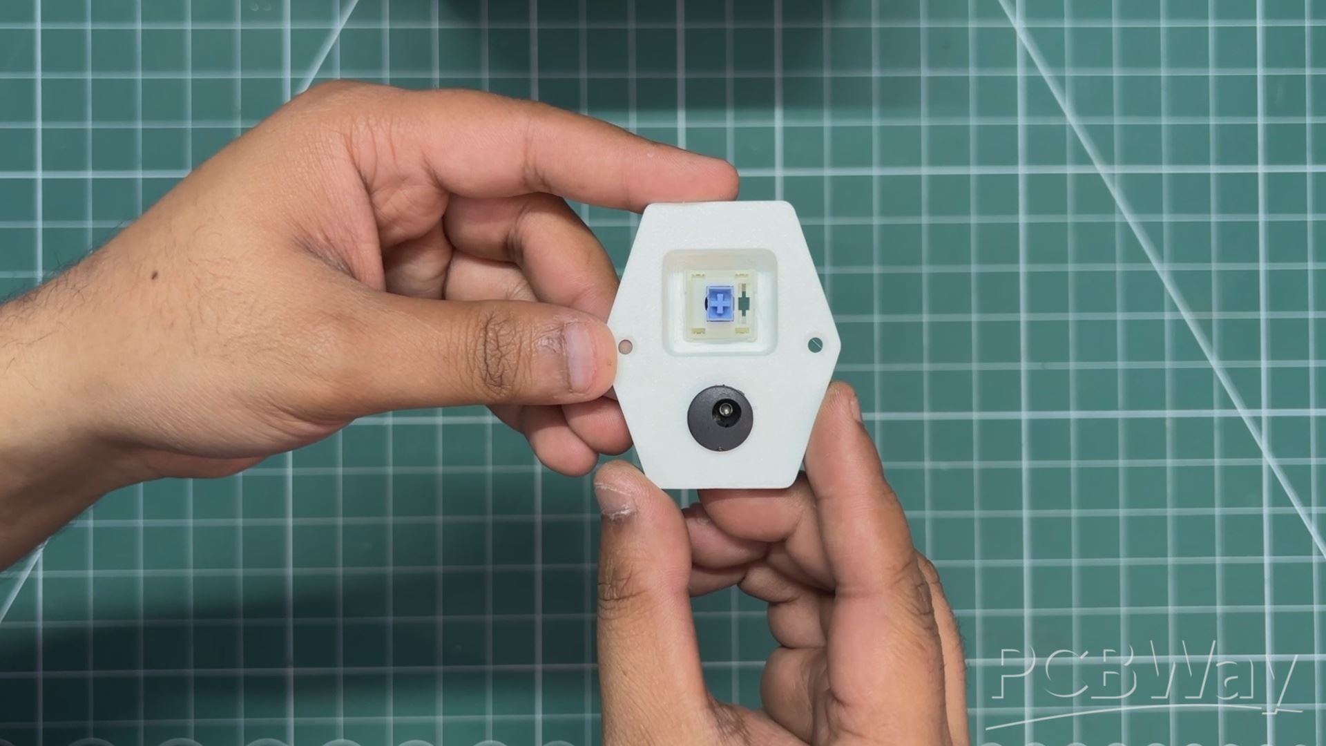
The front of the main body is modeled to closely match the front of the Steam Machine. It features a lower bar section that holds two USB ports on the left side and a push button on the right side. Slightly above the USB ports, there is a light bar that plays LED animations.
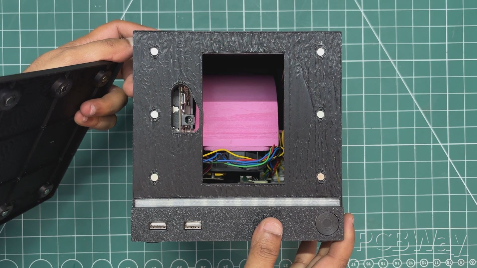
Above this LED bar sits the front cover, which is attached to the main body using magnets. I really like this removable cover design, as it allows for a lot of customization, both aesthetically and electronically.
I also designed a front I/O board PCB that sits behind the LED bar diffuser. This PCB contains RGB LEDs, along with a push button on one side and two USB ports on the other. The PCB is secured in place using four screw bosses, and it also helps hold the LED diffuser and switch actuator in position.
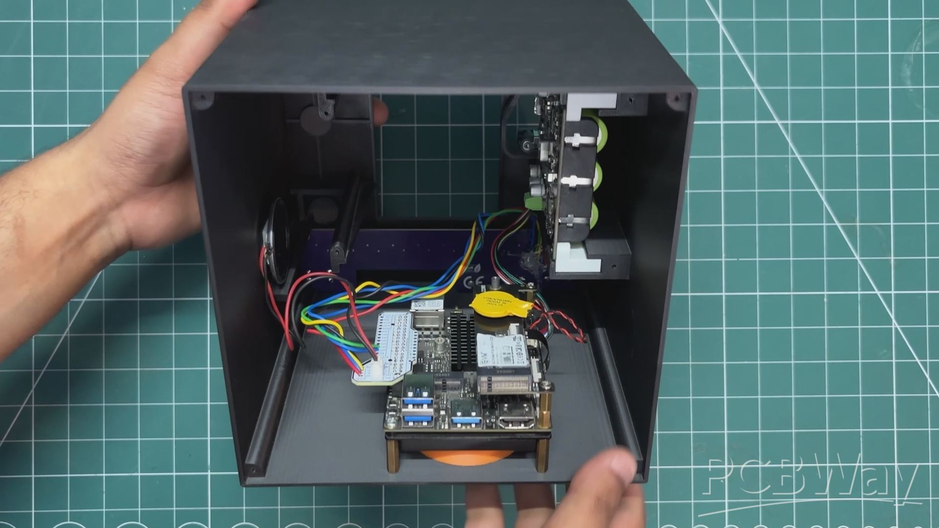
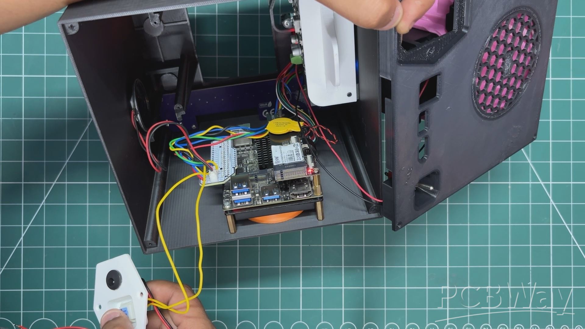
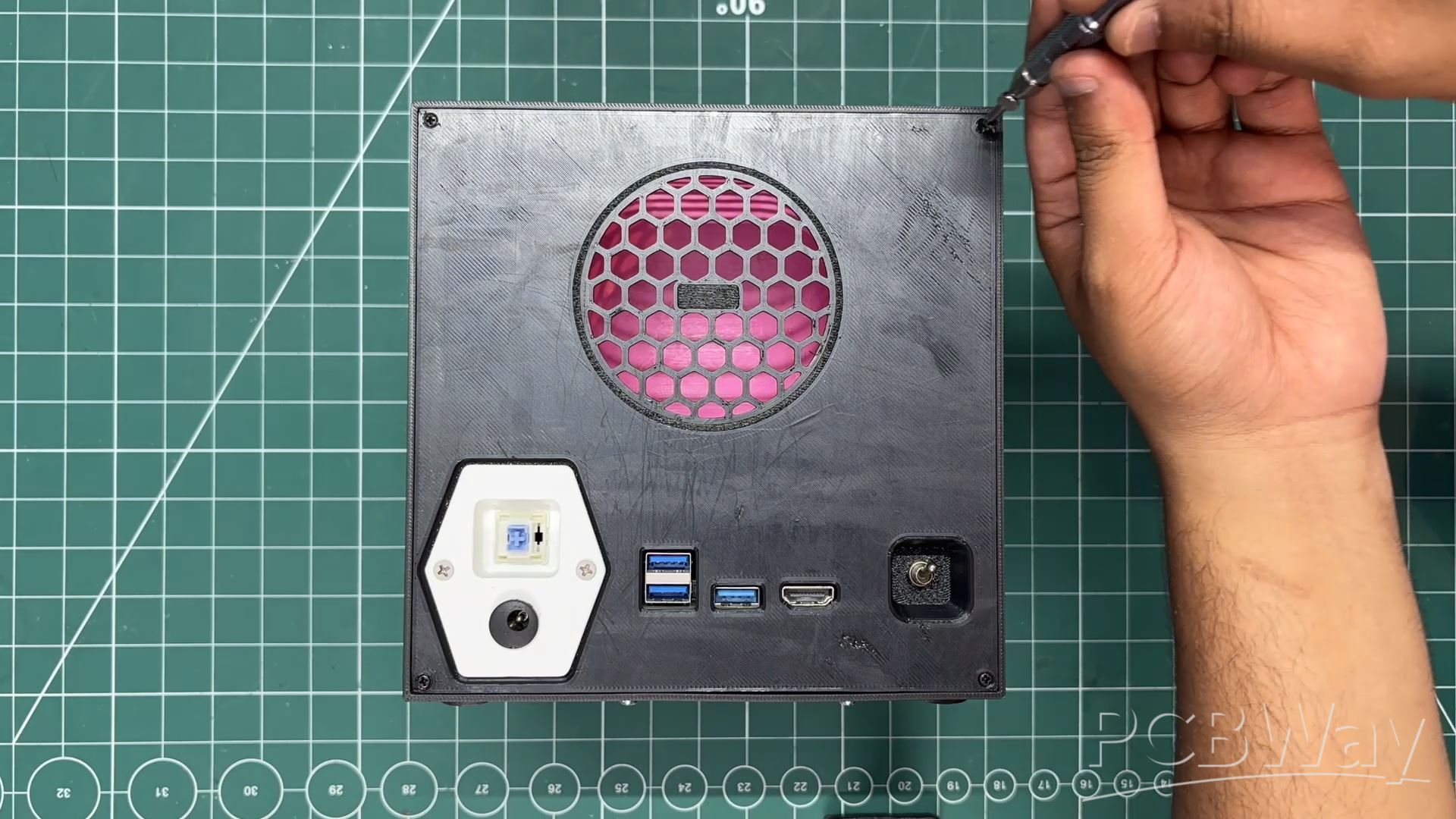
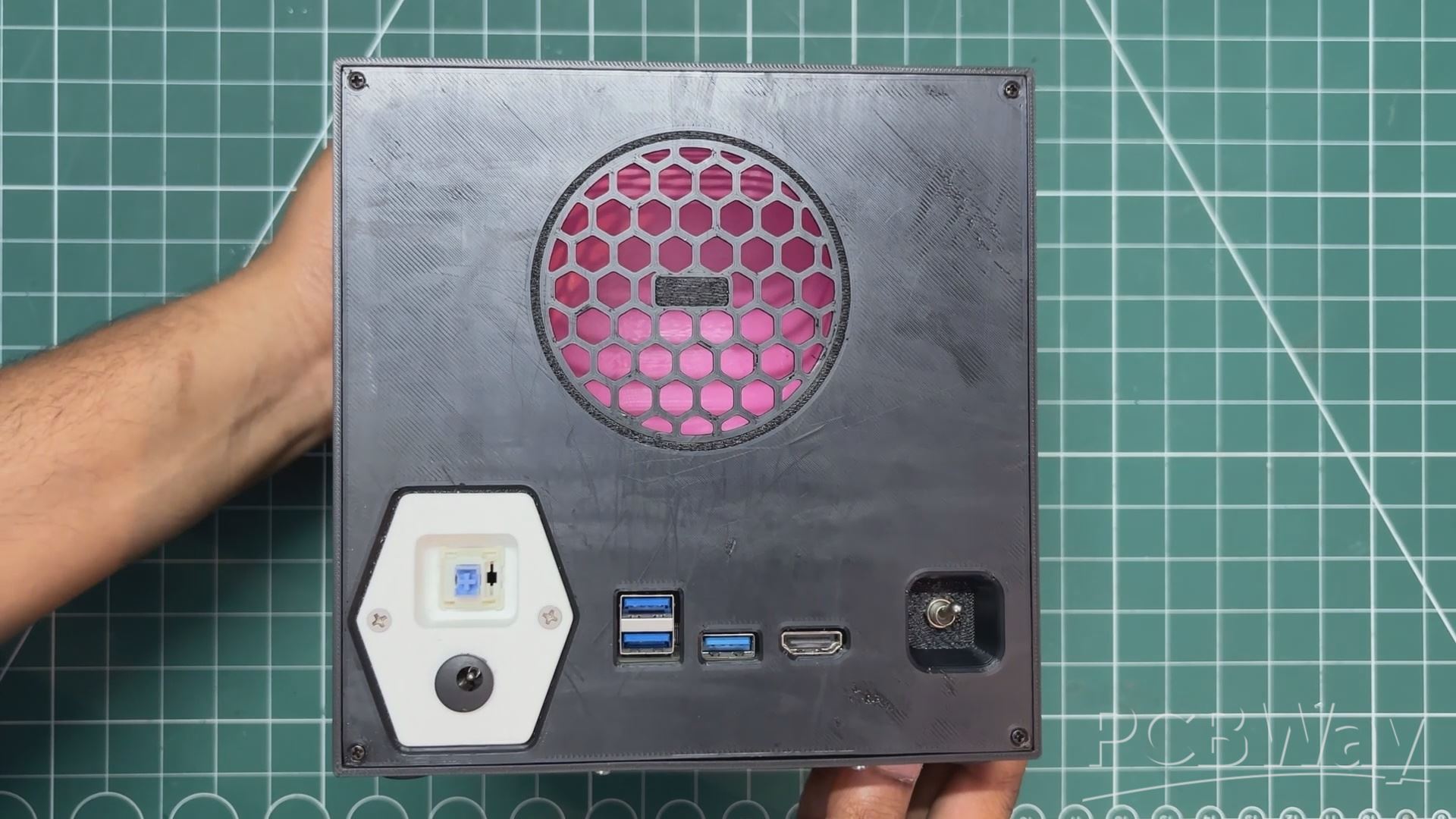
Inside the main body, I installed the LattePanda IOTA, along with its UPS module and an NVMe board connected to it. The IOTA is oriented in such a way that the USB and HDMI ports are accessible from the back side. Openings for these ports are provided in the lid.
On the lid, I designed a mesh grid that houses a 60mm PC fan. To improve airflow, I also modeled an air duct that draws air in through the mesh and directs it straight onto the IOTA. The air is then pulled through the heatsink fan and exhausted out from the bottom of the device.
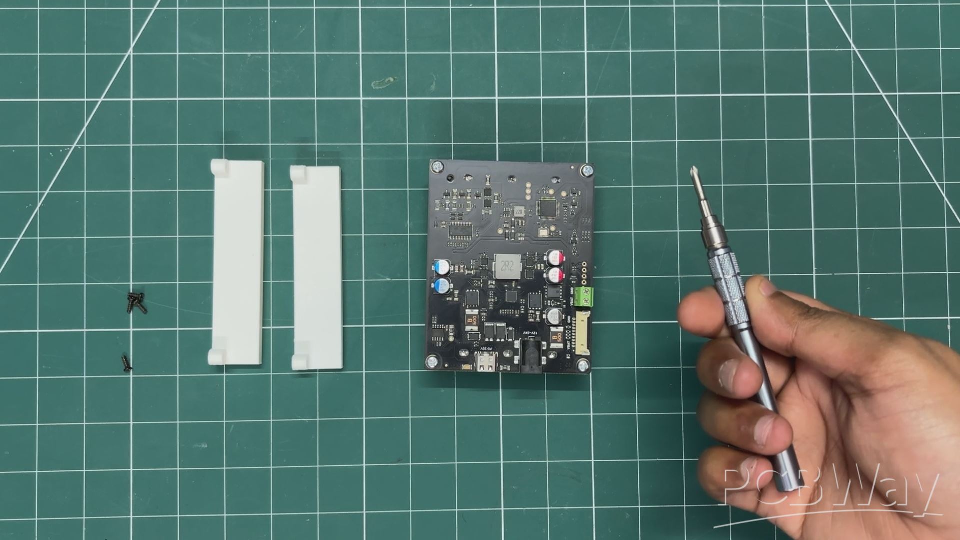
To mount the UPS inside the main body, I designed two holder parts that allow the UPS board to slide into place. To secure it, I added a stopper piece that is screwed down over the UPS board, locking it firmly in position.
To keep the IOTA in position, I used 18mm long PCB standoffs, which are secured to the bottom side of the main body using M2 bolts.
Additionally, I designed a power jack and power button holder that attaches to the lid. This wasn’t part of the original plan. Initially, I intended to include an AC socket and an internal SMPS. However, I later switched to using an external 12V 4A power adapter. This holder now accommodates a standard 5mm DC barrel jack and a mechanical switch, which is used as the power button for the LattePanda.
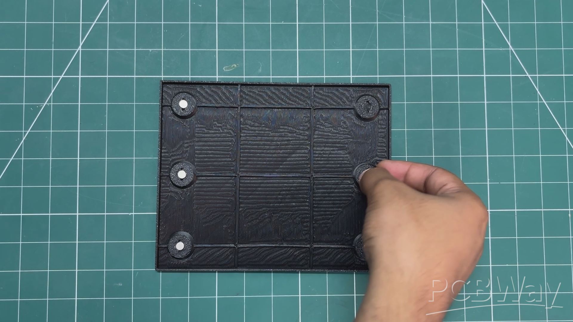
On the front side, the cover is designed to hold magnets. Matching magnets are embedded in both the front cover and the main body, allowing the cover to snap securely into place using magnetism.
By removing the front cover, we can also access the IOTA’s microSD card slot and Ethernet port. While I didn’t need Ethernet since I’m using a USB Wi-Fi adapter, there is also an unpopulated M.2 E-key slot on the IOTA specifically meant for adding a Wi-Fi card.
We added four leg-like features on the bottom side of the main body to lift the whole setup 4 mm off the ground. This space is crucial, as the LattePanda’s heatsink fan draws air from the bottom, and the gap ensures proper exhaust airflow.
Also, to add a design element, I created a large Steam logo on the front cover. The logo itself is a solid part, but the spaces within it are made as separate pieces, which were 3D printed in white PLA. These white parts will later be inserted into the main logo, creating a dual-tone color scheme.
3D PARTS
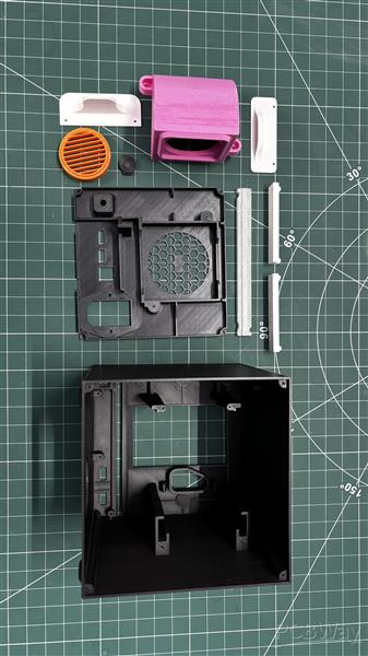
After completing the model, I exported all the parts as 3D mesh files and printed them using an Anycubic Kobra S1 with a 0.4mm nozzle, 0.16mm layer height, 25% gyroid infill, and tree supports. The print settings remained the same for all parts; only the filament color was changed as needed.
The main body, lid, switch, and front cover were printed in black Hyper PLA. The front LED bar was printed using transparent PLA.
Internal parts were printed using whatever filament I had available — for example, the air duct was printed in leftover Hyper Pink PLA, while the UPS holder and stopper were printed in white PLA. The fan grill was printed in orange PLA.
The power jack holder was also printed in white Hyper PLA, along with the Steam logo insert pieces.
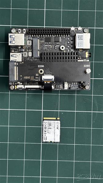
HARDWARE- LATTEPANDA IOTA
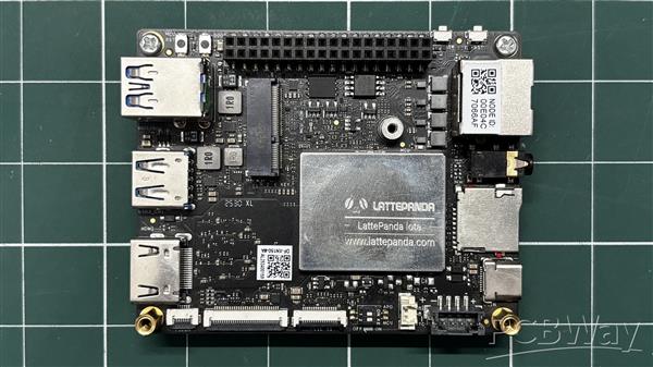
At the heart of this project is the LattePanda IOTA, a compact yet powerful x86 single-board computer designed for edge computing, embedded applications, and serious maker projects. I’m using the 16 GB RAM variant, which provides significantly more headroom than most SBCs of this size.
The LattePanda IOTA shares the same form factor as the original LattePanda V1, but thanks to its newer Intel N150 processor with 4 cores and 4 threads, it can handle much heavier workloads.
We selected the IOTA for this project to build a Steam Machine capable of running Bazzite, making it suitable for low requirement games or even mid-spec. This test we will be doing at the end of the article.
Key Specifications (16 GB Variant)
Processor: Intel x86 CPU (energy-efficient, PC-class architecture)
Memory: 16 GB LPDDR4 RAM
Storage: Onboard eMMC (expandable via M.2 Port)
Connectivity: USB ports for peripherals, HDMI for display output, Ethernet + Wi-Fi (model dependent)
You can check out more about this board from Lattepanda's wiki page.
https://docs.lattepanda.com/content/iota_edition/get_started/
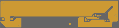
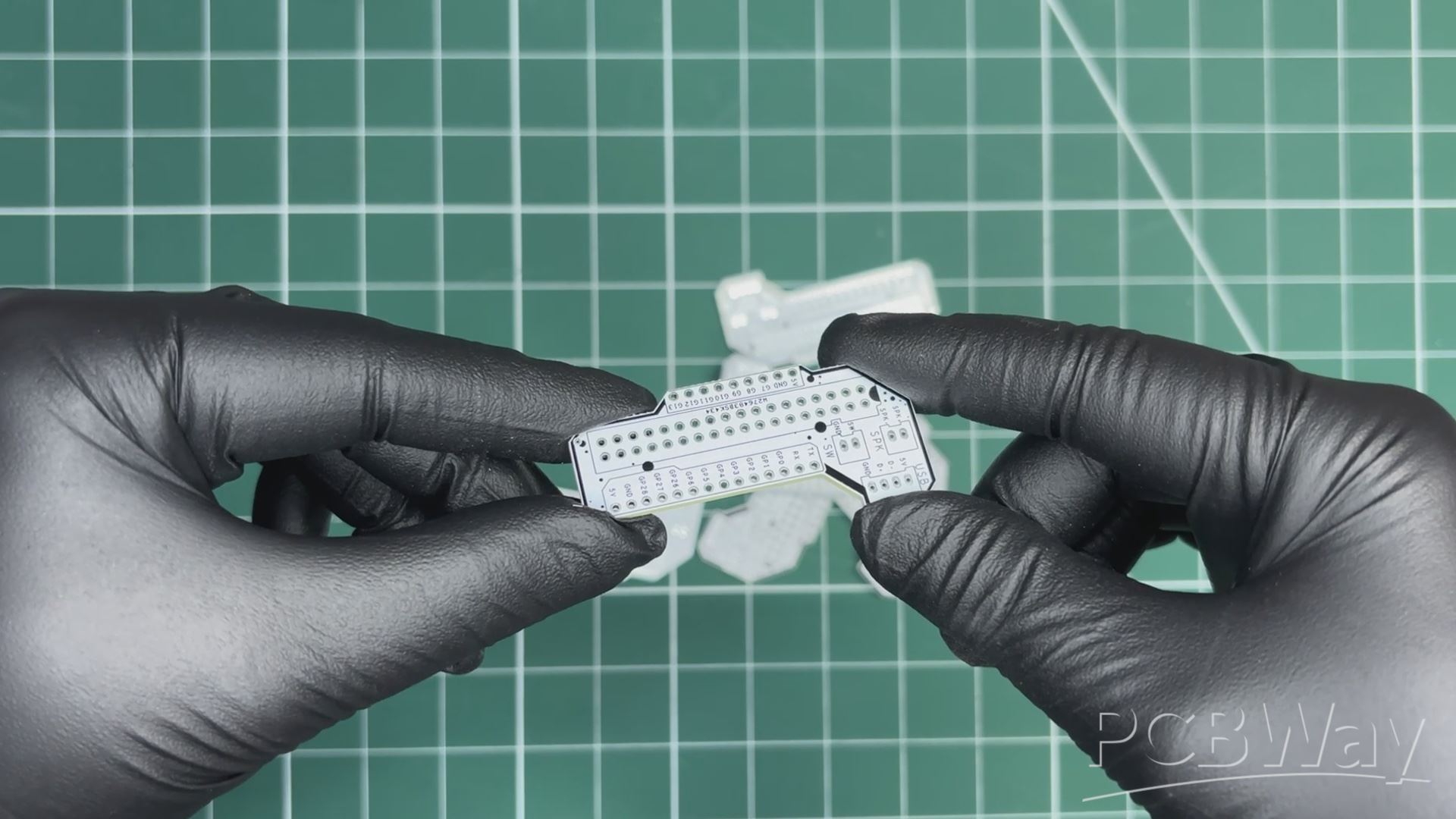
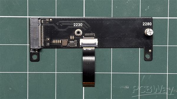
PCB DESIGN - FRONT IO BOARD
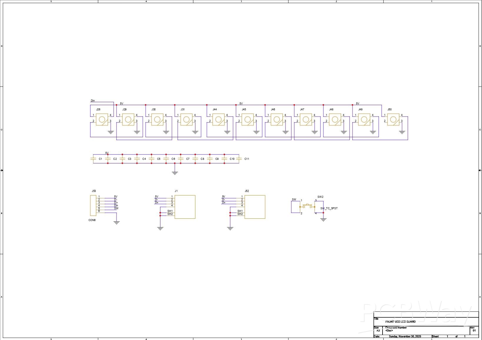
For the front I/O board, we added seven WS2812B LEDs connected in series, where the DOUT of the first LED goes to the DIN of the second, the DOUT of the second goes to the DIN of the third, and so on up to the seventh LED. Each LED has its own decoupling capacitor, for which we used 100nF 0805 package capacitors.
For the USB ports, we used two vertical USB connectors. The VCC of the USB ports and the LEDs are all connected in parallel. The USB ground (GND), LED GND, and push button GND are also connected together. The USB D+ and D? lines are routed to a connector, which is later used to interface the front I/O board with the breakout board.
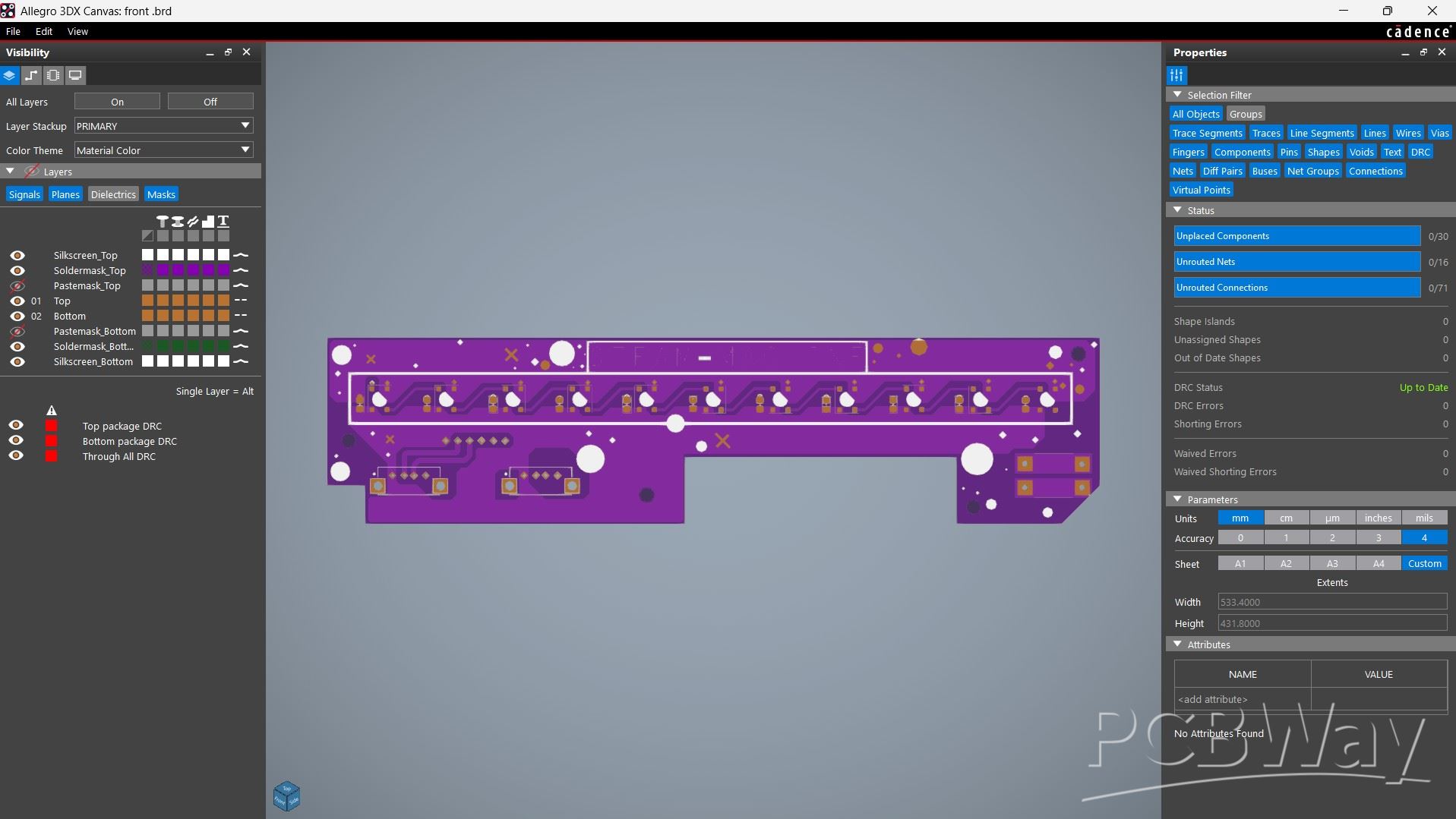
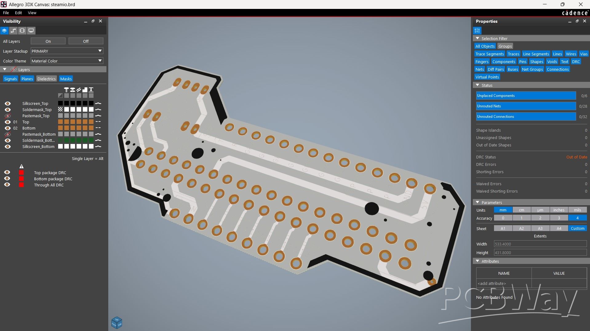
After completing the schematic, we designed the PCB layout using the board outline from the CAD model. This helped us accurately place the mounting holes, USB ports, switch, and LEDs.
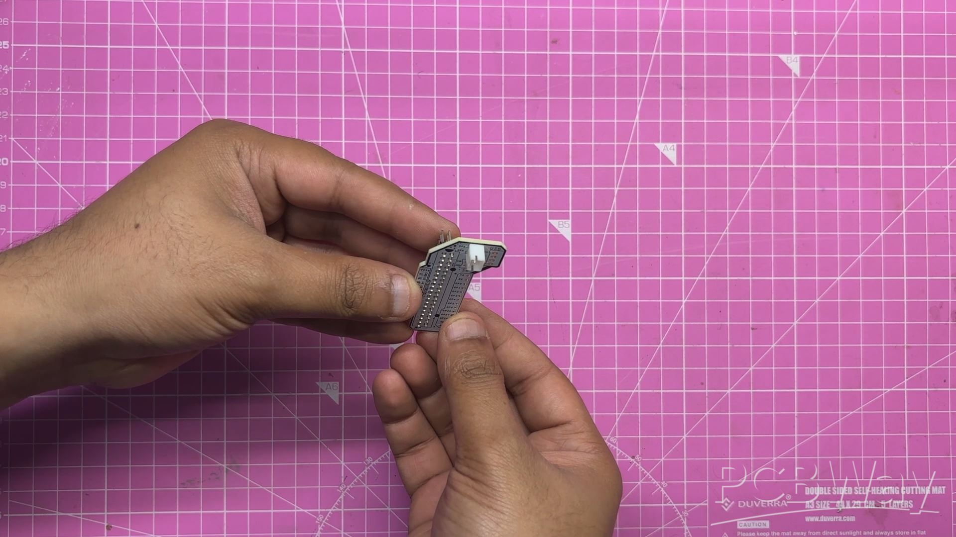
PCB DESIGN - LATTEPANDA IOTA BREAKOUT BOARD
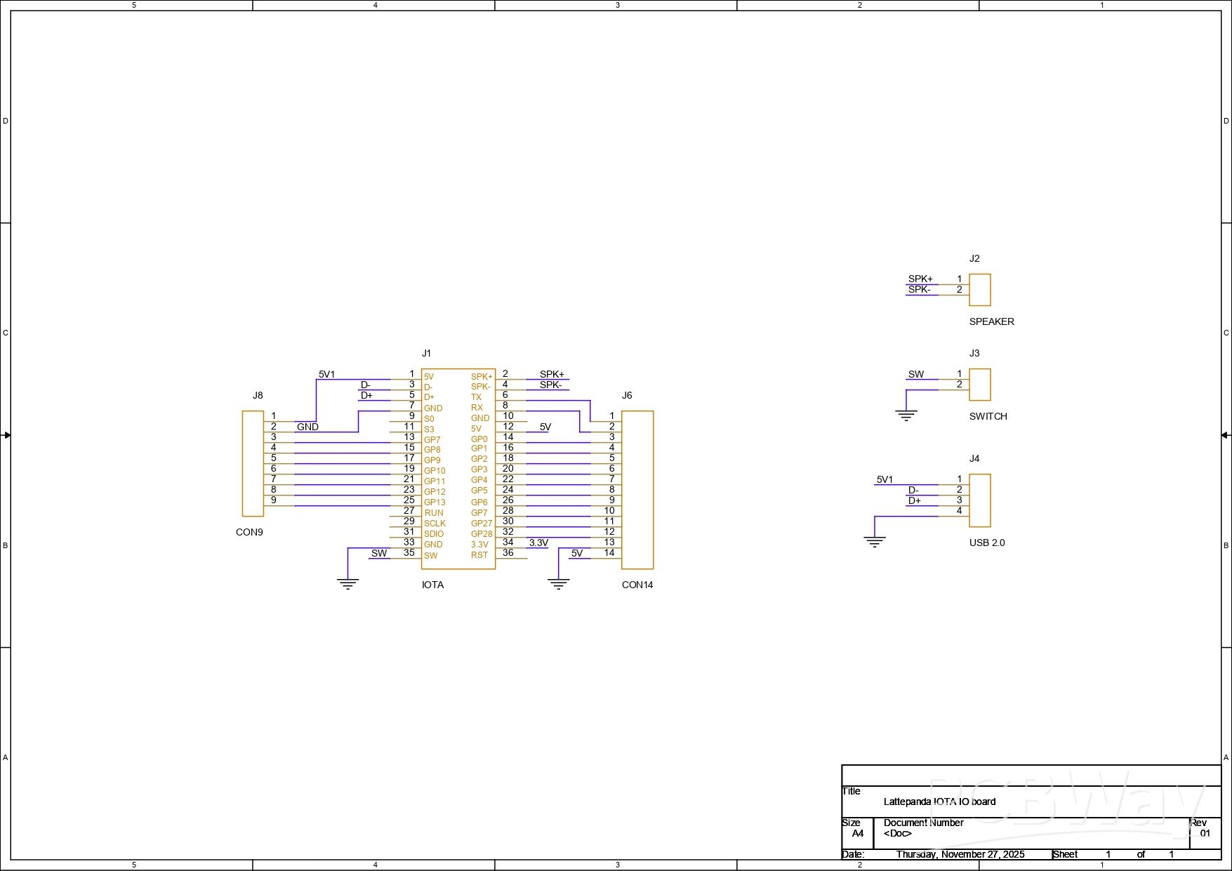
The LattePanda IOTA has proper GPIO headers that include RP2040 pinouts, power switch pins, reset pins, I2C pins, and even a USB 2.0 interface. To make accessing these GPIOs and other peripherals easier, we designed a breakout board that aligns all the GPIO pins on one side of the board, while separating the USB pins, speaker pins, and power switch pins.
We first created the schematic of the setup in our PCB CAD software, using the LattePanda IOTA pinout as a reference. We next converted the schematic into a board layout and designed a minimal board that can also be used in future projects.
PCBWAY SERVICE
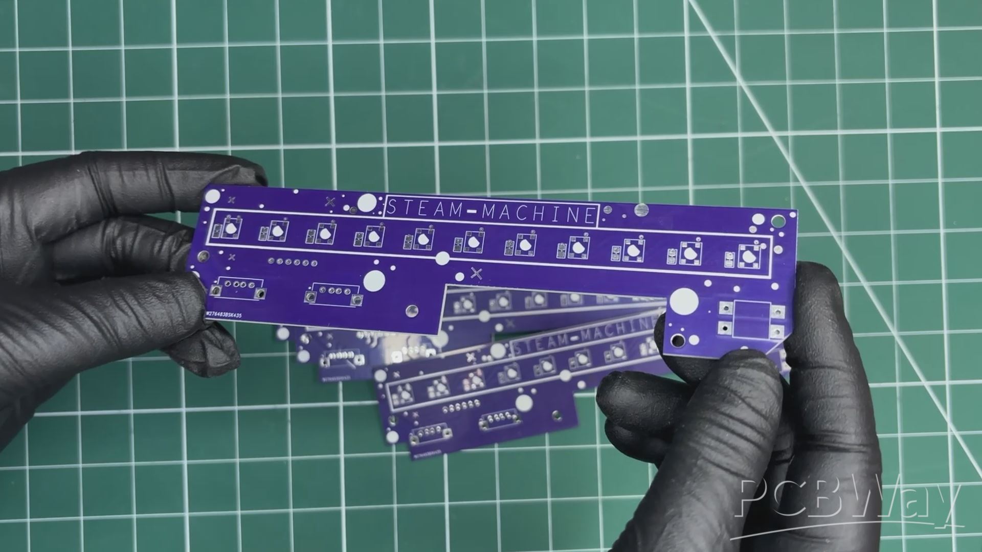
After finalizing the design, I generated the PCB Gerber files and sent them to Wpsload for fabrication. For the Front IO board, I chose a purple PCB with a white solder mask. Alongside it,
I also ordered a second PCB, which was a breakout board for the IOTA GPIO header pins, which was finished with a white solder mask and black silkscreen.
The quality turned out to be excellent with a clean finish, sharp silkscreen, and everything matched the design perfectly.
Over the past ten years, Wpsload has built a strong reputation for providing reliable PCB manufacturing and assembly services, becoming a go-to choice for engineers and makers worldwide.
Honestly, if you’re making custom PCBs and not checking out Wpsload, you’re just making things harder for yourself. They also offer CNC machining and 3D printing services
PCB ASSEMBLY- FRONT IO BOARD
- We begin the front I/O board assembly process by applying solder paste to all the SMD LED pads one by one using a solder paste dispensing syringe. Here, we are using SnPb 63/37 solder paste, which has a melting temperature of around 200°C.
- Next, using tweezers, we pick up and place all seven WS2812B SMD LEDs and seven 100 nF decoupling capacitors in position.
- The board is then placed on a reflow hotplate, which heats the PCB from below up to the solder paste melting temperature. As the temperature exceeds 200°C, the solder paste melts, and all SMD components are secured in place.
- For the through-hole process, we place the 12×12 push button into its position from the front side of the I/O board, followed by two vertical USB ports.
- The board is then flipped over, and all the leads of the through-hole components are soldered using a soldering iron, securing them to their pads and completing the assembly process.
PCB ASSEMBLY- IOTA BREAKOUT BOARD
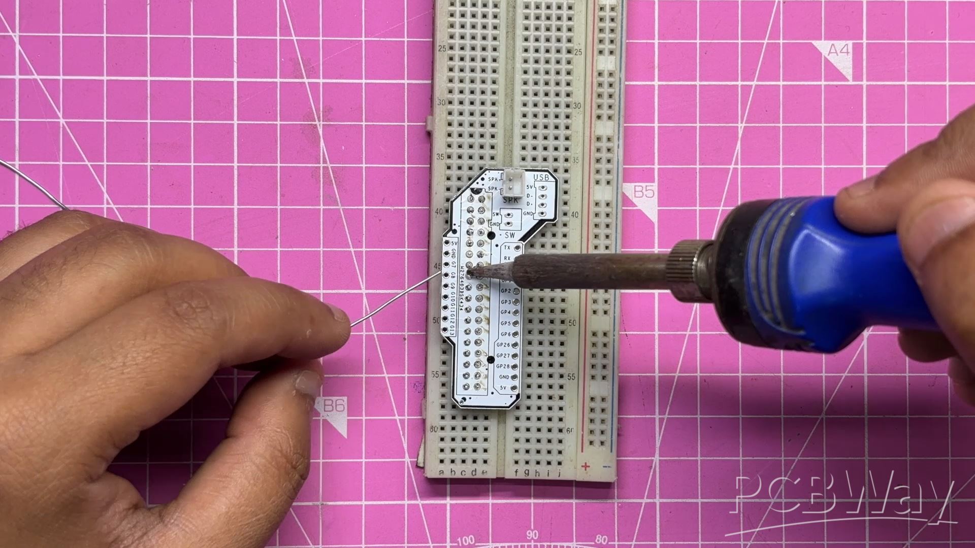
- The assembly for the IOTA breakout board was pretty simple.
- We added two CON18 male header pins side by side to create a CON36 connector.
- On the opposite side, we positioned the CON2 JST connector in place.
- Next, for soldering the header pins, we placed the board on a breadboard. This is a useful pro tip when soldering header pins onto small modules or boards. If you place the header pins into the holes, they can sit slightly misaligned due to the tolerance between the pin and the pad hole. By placing the board on a breadboard, the header pins stay perfectly straight and aligned with the board, making it much easier to solder them cleanly.
- After that, we soldered the pads of the CON2 JST connector, which completed the IOTA breakout board.
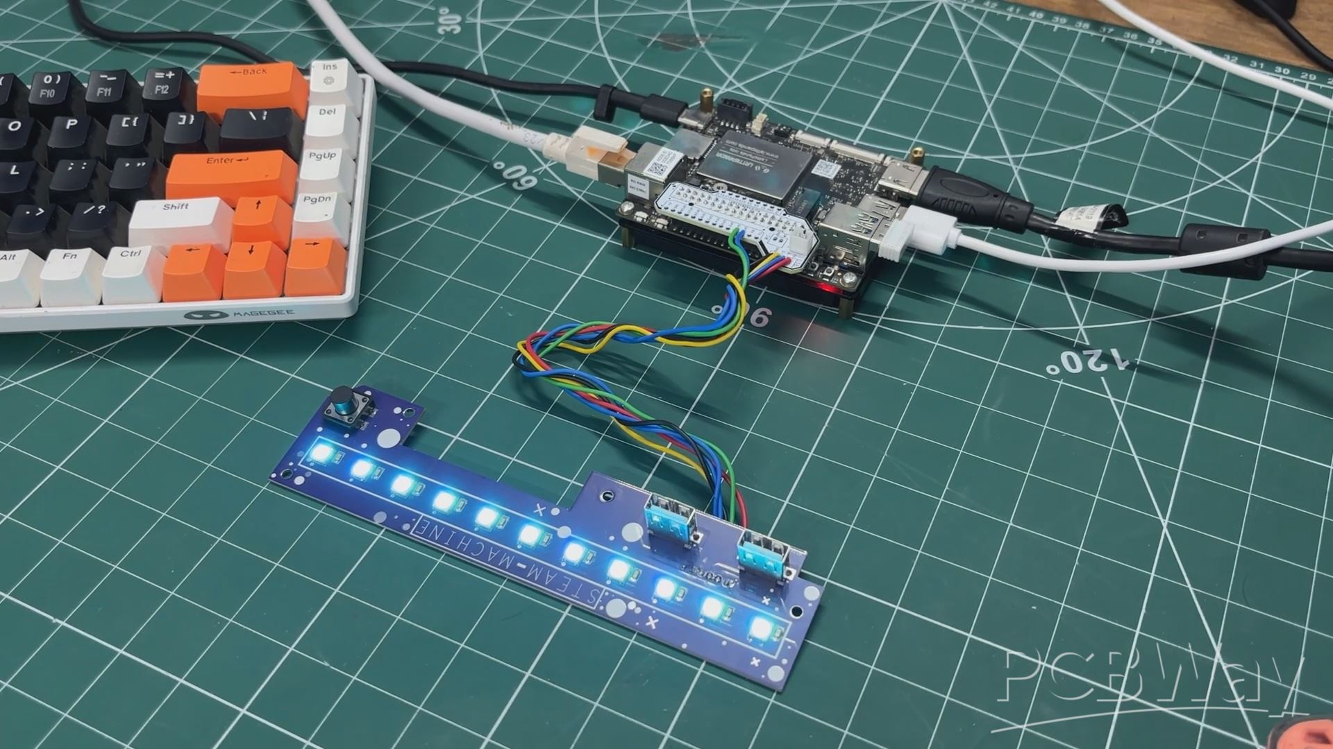
FRONT IO BOARD & IOTA BREAKOUT BOARD SETUP
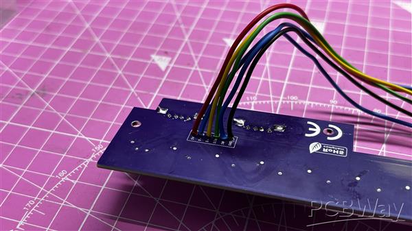
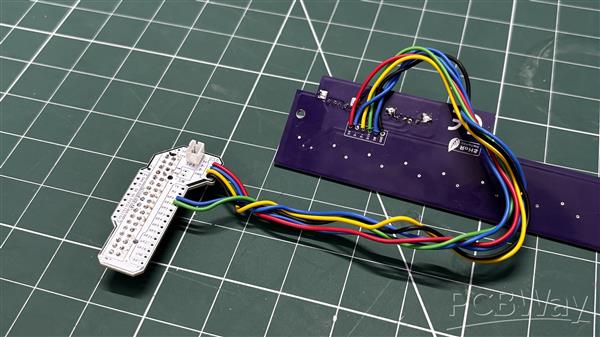
The front I/O board and the LattePanda breakout board are connected together by linking the corresponding pins. First, the 5V pin of the breakout board is connected to the 5V on the front I/O board. The D+ pin is connected to D+ on the front I/O, and similarly, the D? pin is connected to D?.
GPIO1 of the breakout board is connected to the LED DIN pin on the front I/O board, while GND is connected to GND. GPIO0 of the breakout board is connected to the button pin on the front I/O board.
We used single-core silver-copper wire to make all the connections.
IOTA'S RP2040 COPROCESSOR
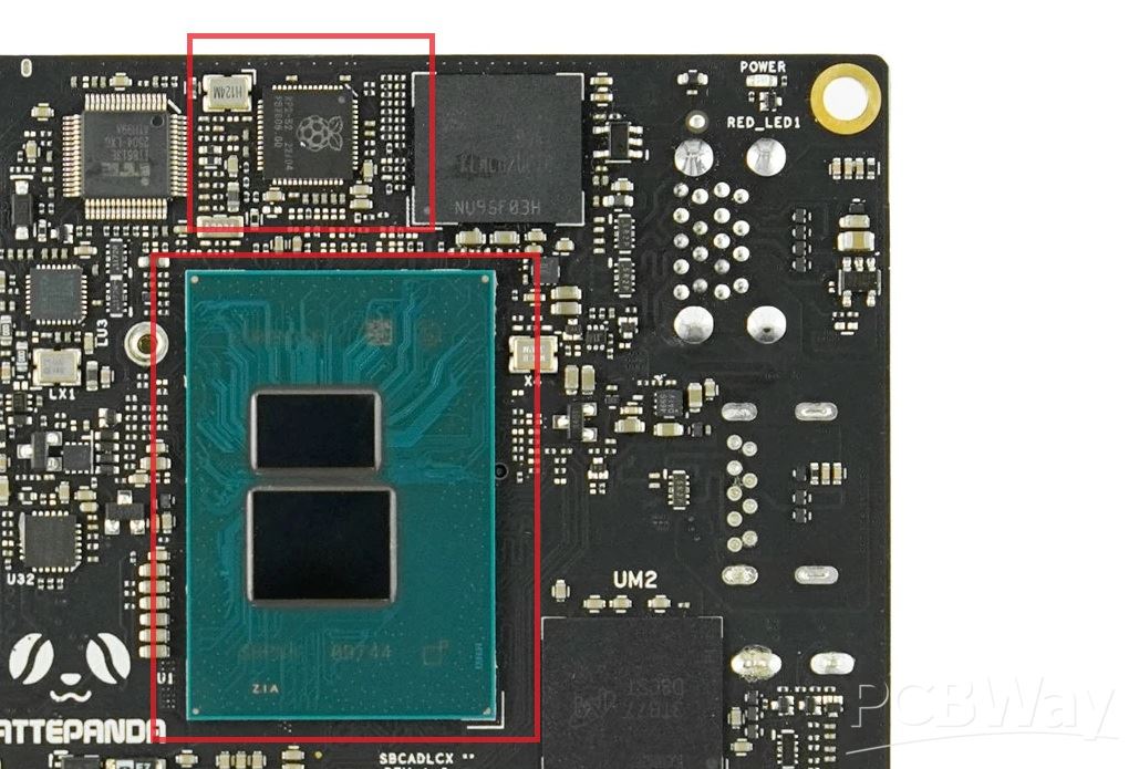
One of the main reasons for using IOTA was not just the Main N150 processor but also the Coprocessor which is embedded in the device.
Intel CPUs have no native GPIO at all. No PWM, no I2C, no SPI. That's just the nature of x86 silicon; it was never designed for that kind of low-level hardware control.
So DFRobot did something really clever. They put an RP2040 coprocessor right on the board, sitting alongside the N150.
This is the same chip used in the Raspberry Pi Pico — dual-core ARM Cortex-M0+ with full GPIO and PWM support. The N150 talks to it over USB serial, and you can flash it straight from Arduino IDE — it just shows up as a COM port.
I plan to use this RP2040 for controlling the RGB LEDs of the front IO Board.
The RP2040 drives the whole RGB LED Strip on a single data line and runs several different lighting animations—all completely independently from SteamOS running on the N150.
This isn't even a new idea for LattePanda. Their original V1 board from nearly a decade ago shipped with an ATmega328P, which was the same chip used in Arduino Nano. DFRobot basically invented the x86 plus microcontroller SBC, and they've been refining it ever since.
CODE
Here's the Main code we prepared for our project, and it's a simple one; let's have a quick breakdown.
#include <Adafruit_NeoPixel.h>
#define LED_PIN 1
#define BTN_PIN 0
#define NUM_LEDS 11
#define BRIGHTNESS 80
Adafruit_NeoPixel strip(NUM_LEDS, LED_PIN, NEO_GRB + NEO_KHZ800);
int mode = 0;
const int TOTAL_MODES = 7;
int lastBtnState = HIGH;
unsigned long lastDebounce = 0;
const unsigned long DEBOUNCE_MS = 50;
uint32_t TEAL = strip.Color(0, 200, 180);
uint32_t RED_COLOR = strip.Color(180, 0, 0);
unsigned long lastUpdate = 0;
int animStep = 0;
float breathVal = 0.0;
float breathDir = 1.0;
void setup() {
strip.begin();
strip.setBrightness(BRIGHTNESS);
strip.show();
pinMode(BTN_PIN, INPUT_PULLUP);
}
void loop() {
handleButton();
runAnimation();
}
void handleButton() {
int reading = digitalRead(BTN_PIN);
if (reading != lastBtnState) lastDebounce = millis();
if ((millis() - lastDebounce) > DEBOUNCE_MS) {
if (reading == LOW) {
mode = (mode + 1) % TOTAL_MODES;
animStep = 0;
breathVal = 0.0;
breathDir = 1.0;
strip.clear();
strip.show();
delay(200);
}
}
lastBtnState = reading;
}
void runAnimation() {
switch (mode) {
case 0: modeSteadyTeal(); break;
case 1: modeChase(); break;
case 2: modeBreathingTeal(); break;
case 3: modeComet(); break;
case 4: modeRainbowFlow(); break;
case 5: modeSolidRed(); break;
case 6: modeRedPulse(); break;
}
}
void modeSteadyTeal() {
if (millis() - lastUpdate < 500) return;
lastUpdate = millis();
for (int i = 0; i < NUM_LEDS; i++) strip.setPixelColor(i, TEAL);
strip.show();
}
void modeChase() {
if (millis() - lastUpdate < 60) return;
lastUpdate = millis();
strip.clear();
strip.setPixelColor(animStep % NUM_LEDS, TEAL);
strip.show();
animStep++;
}
void modeBreathingTeal() {
if (millis() - lastUpdate < 20) return;
lastUpdate = millis();
breathVal += breathDir * 2.0;
if (breathVal >= 255) { breathVal = 255; breathDir = -1; }
if (breathVal <= 0) { breathVal = 0; breathDir = 1; }
float f = breathVal / 255.0;
uint32_t c = strip.Color(0, (int)(200 * f), (int)(180 * f));
for (int i = 0; i < NUM_LEDS; i++) strip.setPixelColor(i, c);
strip.show();
}
void modeComet() {
if (millis() - lastUpdate < 50) return;
lastUpdate = millis();
for (int i = 0; i < NUM_LEDS; i++) {
uint32_t c = strip.getPixelColor(i);
uint8_t r = ((c >> 16) & 0xFF) * 0.5;
uint8_t g = ((c >> 8) & 0xFF) * 0.5;
uint8_t b = ( c & 0xFF) * 0.5;
strip.setPixelColor(i, strip.Color(r, g, b));
}
strip.setPixelColor(animStep % NUM_LEDS, TEAL);
strip.show();
animStep++;
}
void modeRainbowFlow() {
if (millis() - lastUpdate < 30) return;
lastUpdate = millis();
for (int i = 0; i < NUM_LEDS; i++) {
int hue = ((animStep * 3 + i * (65536 / NUM_LEDS)) & 0xFFFF);
strip.setPixelColor(i, strip.gamma32(strip.ColorHSV(hue, 255, 200)));
}
strip.show();
animStep++;
}
void modeSolidRed() {
if (millis() - lastUpdate < 500) return;
lastUpdate = millis();
for (int i = 0; i < NUM_LEDS; i++) strip.setPixelColor(i, RED_COLOR);
strip.show();
}
void modeRedPulse() {
if (millis() - lastUpdate < 20) return;
lastUpdate = millis();
breathVal += breathDir * 2.0;
if (breathVal >= 255) { breathVal = 255; breathDir = -1; }
if (breathVal <= 0) { breathVal = 0; breathDir = 1; }
float f = breathVal / 255.0;
uint32_t c = strip.Color((int)(180 * f), 0, 0);
for (int i = 0; i < NUM_LEDS; i++) strip.setPixelColor(i, c);
strip.show();
}
Here I have a simple sketch built around the Adafruit Neopixel Library. I have added a total of seven animation modes, which are toggled by a button press. This is handled by the handleButton() function; I even added debouncing so it doesn't misfire.
Each mode is its own function.
- modeSteadyteal() for default teal idle glow
- modeChase() is for a single Pixel (teal color) to sweep across the strip.
- modeBreathingTeal() is for a slow fade in and fade out.
- modeComet() is for a moving pixel with a decaying tail inspired by a comet, hence the name.
- mode RainbowFlow() is for a rainbow-colored light strip.
- modeSolidRed() is for a flat red glow.
- modeRedPulse() is for a breathing red effect.
We haven't used delays in our function and instead went with millis, so the button stays responsive at all times; the runAnimation function just reads the current mode and calls whichever function belongs to it.
More Functions could be added, but I was satisfied with the result, so seven modes were good. This can be edited easily by adding a new function and editing the code slightly.
PROGRAMMING THE ONBOARD RP2040
Flashing the onboard RP2040 chip is pretty straightforward — it’s basically a Pico. We first boot into Windows, which comes preinstalled on the eMMC chip.
We then navigate to Tools>Board>Board Manager, search for “Pico,” and install Raspberry Pi Pico/RP2040 by Earle F. Philhower. After waiting for the installation to complete, we select Raspberry Pi Pico as the main board and open our previously written sketch.
Now comes the critical part. When we navigate to the Tools menu, we may see that no COM port is selected, and at first, the Pico might not be visible.
To fix this, press and hold the BOOTSEL button, then press and release the RST button, and finally release the BOOTSEL button. This will allow the OS to detect the RP2040 as a mass storage device. We can then select the COM port (which appears as a UF2 board) and hit upload.
After uploading, the LED will start functioning. It doesn’t matter if the OS is removed, as long as the IOTA is powered, the RP2040 will continue to function normally, and the LED will work.
There is also a complete wiki article covering the entire programming process of the RP2040, along with other details about the board, so make sure to check that out.
https://docs.lattepanda.com/content/iota_edition/rp2040_programming_arduino/#preparation
USB PORT TEST
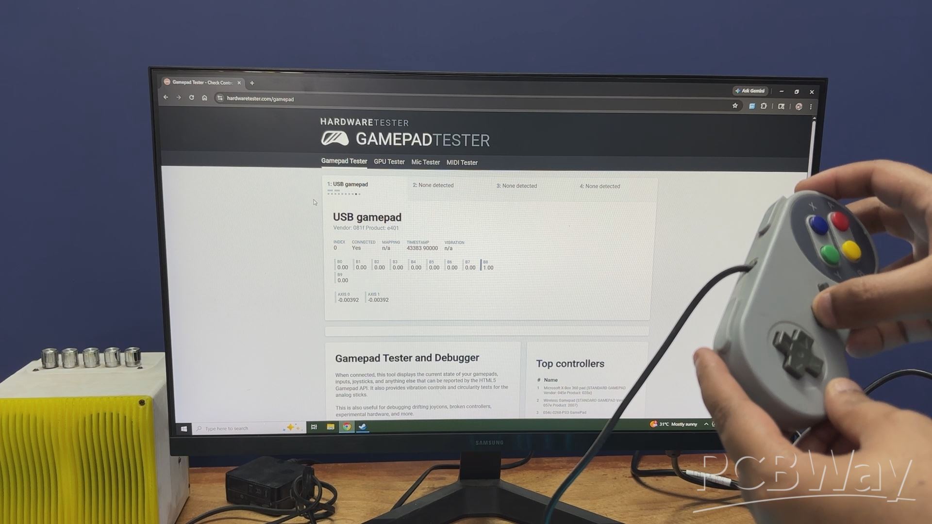
For testing the USB ports, I used a USB NES-style controller (it’s not actually a NES controller; it just looks like one). I plugged the controller into the first port and used an online gamepad tester tool. By pressing the buttons on the controller, the inputs were registered on the display, confirming that the setup was functioning correctly. I repeated the same process for the second USB port as well.
According to the documentation provided by LattePanda, the D+ and D? pins available on the GPIO headers (which I am using) support USB 2.0 speeds. This is perfectly fine for connecting devices like game controllers, pen drives, mouse, keyboards, or SD card adapters for data transfer. While the speeds are limited to USB 2.0, it works reliably for these use cases.
https://hardwaretester.com/gamepad
HEATSINK
During my usual Lattepanda IOTA run, the top part was getting slightly warm, so I added a 40mm x 30mm aluminum heatsink to counter the heat issue.
This passive heatsink helps dissipate minor heat, keeping the IOTA cool from above. Additionally, we integrated a PC fan that circulates air inside the steam machine. The fan will help keep this heatsink cool.
IOTA UPS BOARD
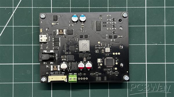
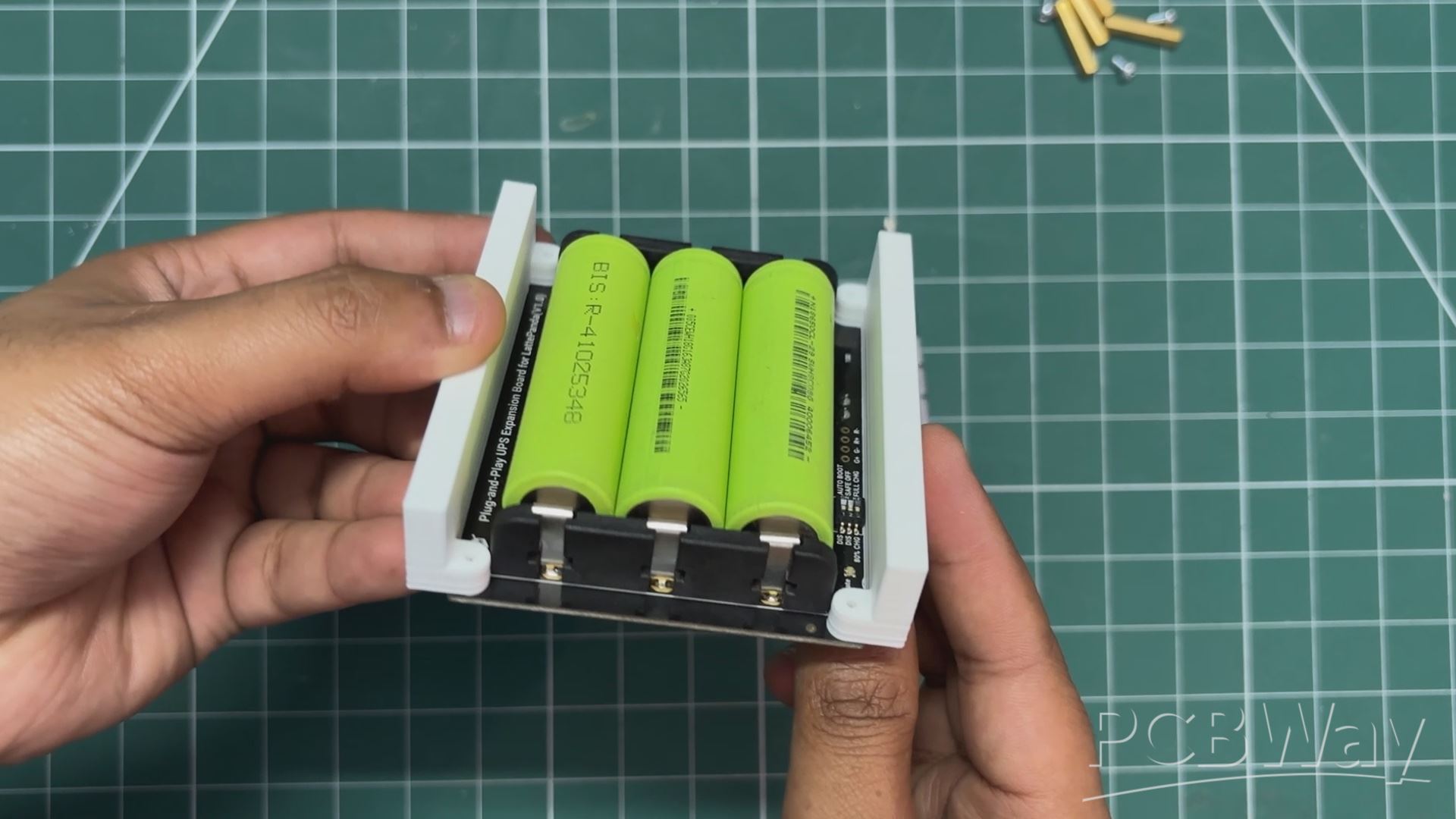
For the primary power source of this project, I am using the Smart UPS Expansion Board for the LattePanda IOTA. As the name suggests, this is a UPS board powered by three 18650 Li-ion cells, and it provides a stable power source for the IOTA.
It features two power input options. The first is a USB Type-C port that supports 20V PD input, and the second is a standard 5mm DC barrel jack, which accepts input voltage between 12V and 24V. The minimum power required for charging this UPS board is under 36W.
The standby current of the setup is around 30?A, which makes this board very useful for projects where it remains connected to the IOTA for long periods, as the battery will not drain quickly.
Wiki page- https://wiki.dfrobot.com/dfr1247/#tech_specs
UPS BOARD ASSEMBLY
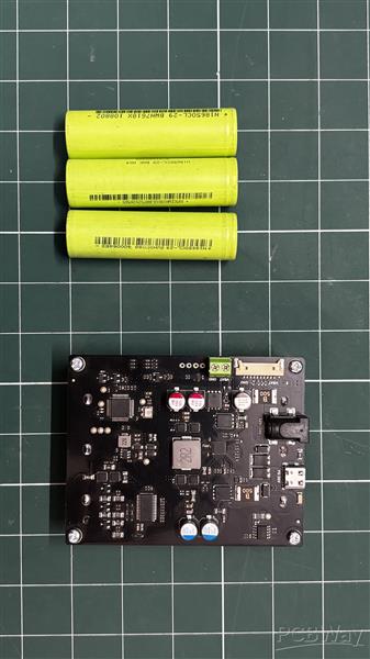
- The UPS board assembly begins with placing three lithium-ion cells into the cell holder on the UPS board, one by one. It is important to ensure correct polarity while inserting the cells. The UPS board has clearly marked positive terminals, and each cell’s positive side must be aligned accordingly. If inserted incorrectly, the entire setup could short.
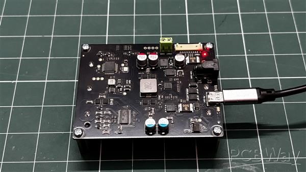
- Next, we connect the 10-pin power cable; one end goes to the CON10 connector on the UPS board, and the other end connects to the CON10 port on the LattePanda. This links the UPS board with the LattePanda.
- After connecting a monitor through HDMI Display and pressing the power switch on the LattePanda, the entire setup powers on, and we can see Bazzite loading.
For charging, we use a 60W PD charger along with a USB power meter. Through this, we connect a PD cable and monitor the charging cycle. During charging, the UPS board draws a stable 12V from the charger, with current varying between 1A and 2A throughout the process.
PCIE TO M.2 HAT
The LattePanda IOTA comes with an onboard PCIe expansion port, similar to the Raspberry Pi 5, which means we can add a variety of expansion boards with it, starting with an M.2 NVMe expansion HAT.
My idea is to use an NVMe SSD for booting the OS so that the whole setup feels fast.
M.2 HAT ASSEMBLY
- We begin the M.2 HAT assembly by connecting the mounting holes of the LattePanda with PCB standoffs.
- Next, we pair the M.2 HAT’s PCIe FFC connector with the FFC connector on the LattePanda IOTA.
- We then align the mounting holes of the M.2 HAT with the PCB standoffs and use M2.5 screws to secure both together.
- Finally, we install a Gen3 NVMe SSD into the M.2 M-key socket, completing the assembly of the LattePanda with the M.2 HAT.
OS- BAZZITE
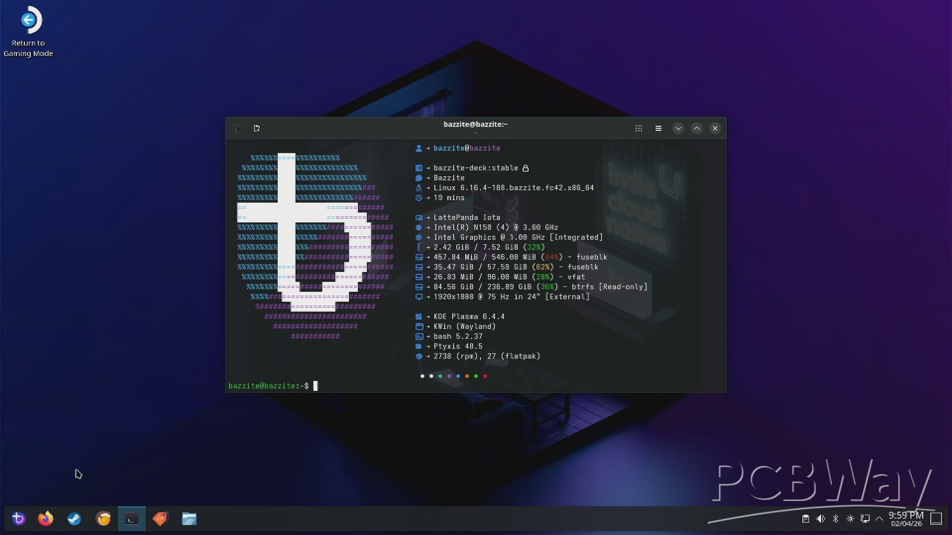
Originally, I wanted to use SteamOS because I was building a Steam Machine, and SteamOS would have been the ideal choice. However, SteamOS works best with AMD hardware, while the IOTA uses an Intel N150 processor. I did try installing SteamOS, as some people have managed to get it working, but it just wasn’t compatible with my current setup. So, I went with the next best option—Bazzite.
Bazzite is a Linux-based operating system focused on gaming, built on Fedora and optimized for running Steam and other PC games, making it a great fit for compact x86 systems like the LattePanda IOTA.
BAZZITE SETUP
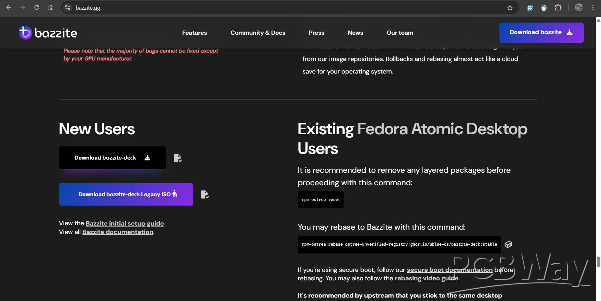
To download Bazzite, I first visited the official Bazzite website and navigated to the download page. From the hardware selection menu, I chose Desktop as the target platform. Next, I selected Intel UHD/HD/Iris as the GPU option, since the LattePanda IOTA uses Intel integrated graphics. For the desktop environment, I chose KDE.
https://bazzite.gg/#image-picker
After filling in these options, we were presented with two images: Bazzite Deck and Bazzite Deck Legacy. We went ahead with the standard Bazzite Deck image. It’s also worth noting that if you’re already running a Fedora Atomic desktop, Bazzite can be installed by rebasing instead of doing a fresh installation.
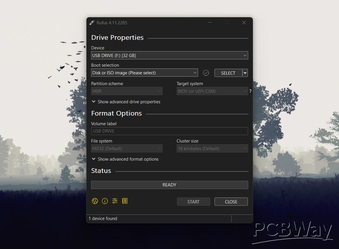
To make the bootable USB, we used Rufus. We first plugged in a USB drive and opened Rufus, which automatically detected it. Then we selected the Bazzite ISO file and left all the settings exactly as they were—MBR for the partition scheme and BIOS as the target system.
After hitting Start, Rufus did its thing, and a couple of minutes later, the bootable drive was ready to go.
In the BIOS, we go to the boot menu and select the bootable USB to start the installation process. After a few minutes, we’re taken to the Bazzite installer, where we select the installation language.
From there, we head to System, then to Installation Destination, and choose our NVMe SSD as the primary storage. Once that’s done, we start the installation. The whole process takes around 15 to 20 minutes, and after it finishes, we’re booted straight into Bazzite.
I have prepared a detailed article about installing Bazzite that goes in-depth into the entire process on a similar single-board computer. You can check it out using the link below.
https://www.hackster.io/Arnov_Sharma_makes/bazzite-on-lattepanda-mu-setting-up-guide-4c93b4
UPS BOARD HOLDER ASSEMBLY
At this stage, with the OS ready, we begin the assembly process of the entire setup.
- This starts with placing the UPS board holders onto the mounting holes of the UPS board.
- We use four M2 screws to securely fasten the holders to the UPS board.
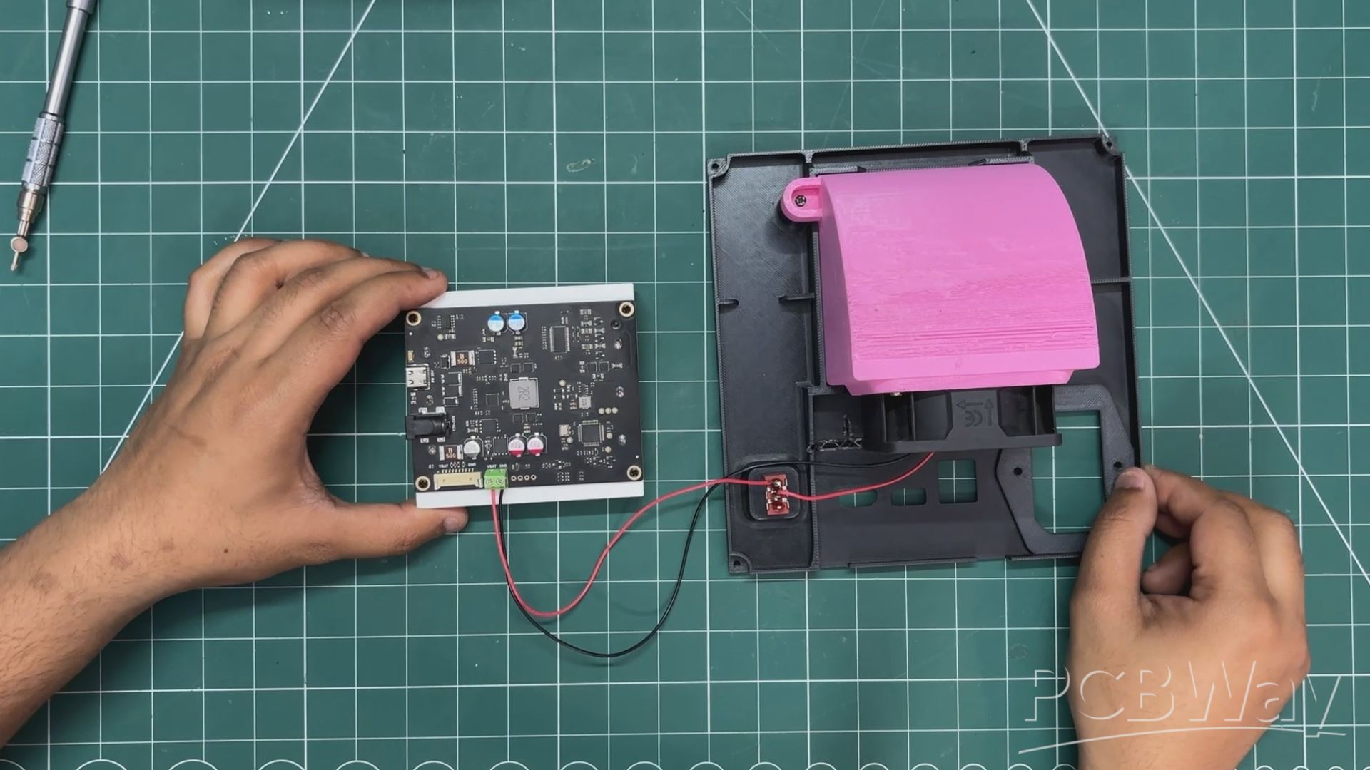
MAIN ELECTRONICS SETUP
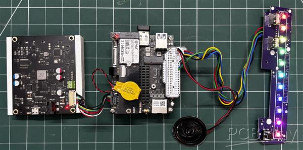
- We plug a 4Ω 1W speaker into the CON2 JST connector of the breakout board and then reconnect the breakout board to the GPIO header of the LattePanda IOTA.
- Next, we connect the BIOS battery of the LattePanda by plugging its JST connector into the corresponding connector on the board. The BIOS battery has double-sided tape, so we peel off the protective cover and attach it to a free space on the M.2 HAT.
- We then reconnect the UPS CON10 cable to the LattePanda.
At this point, the core electronics setup of the project is complete. Now, we just need to assemble everything into the main body.
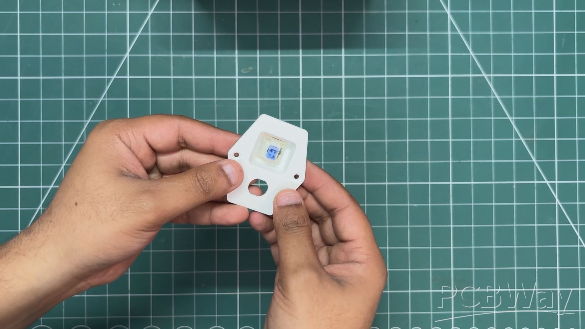
MAIN BODY FRONT IO BOARD ASSEMBLY
- For this step, we take the switch actuator and position it in place from the inside of the main body.
- Next, we place the LED bar diffuser and align it properly.
- The front I/O board is then positioned over the LED bar diffuser and switch actuator. It is mounted in place using four M2 screws.
SPEAKER ASSEMBLY
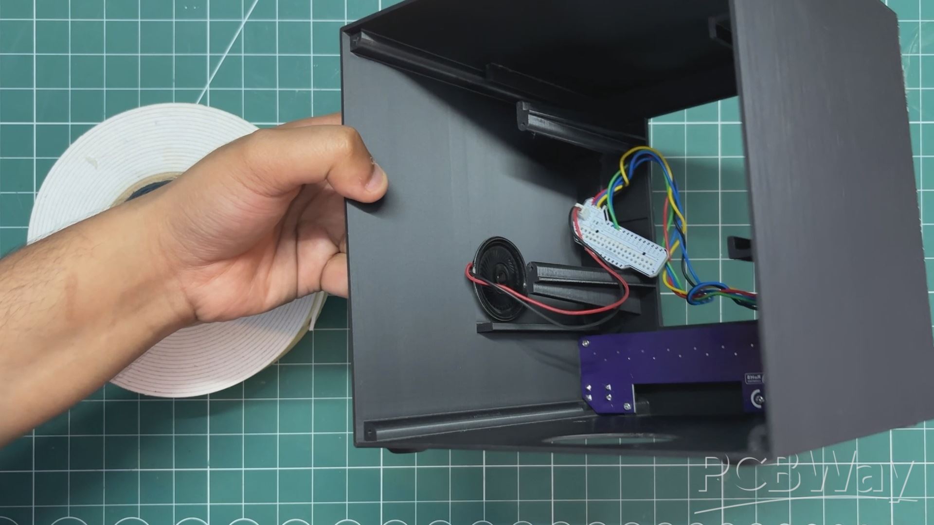
- We use a piece of double-sided foam tape and attach it to the speaker.
- After peeling off the protective layer from the other side, we place the speaker in an empty space inside the enclosure.
- Pressing it firmly ensures that the foam tape secures the speaker in place.
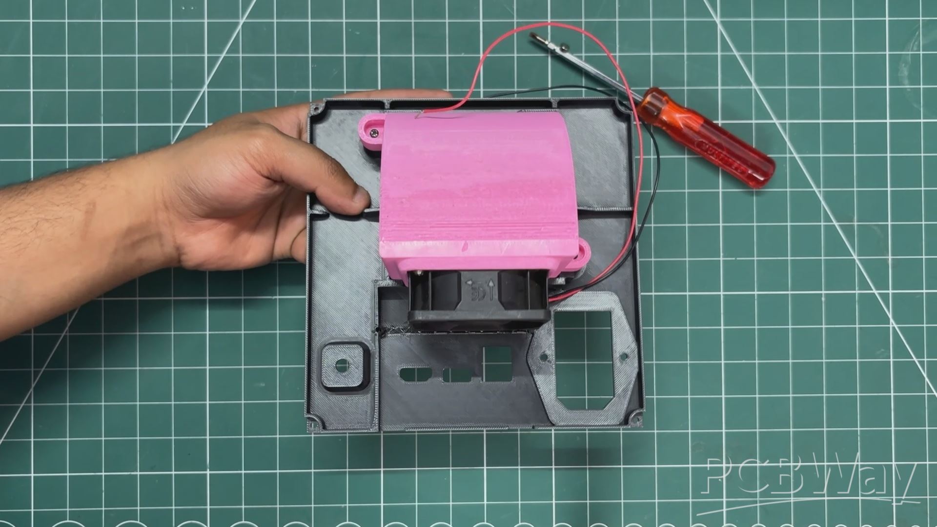
MAIN BODY & IOTA SETUP ASSEMBLY
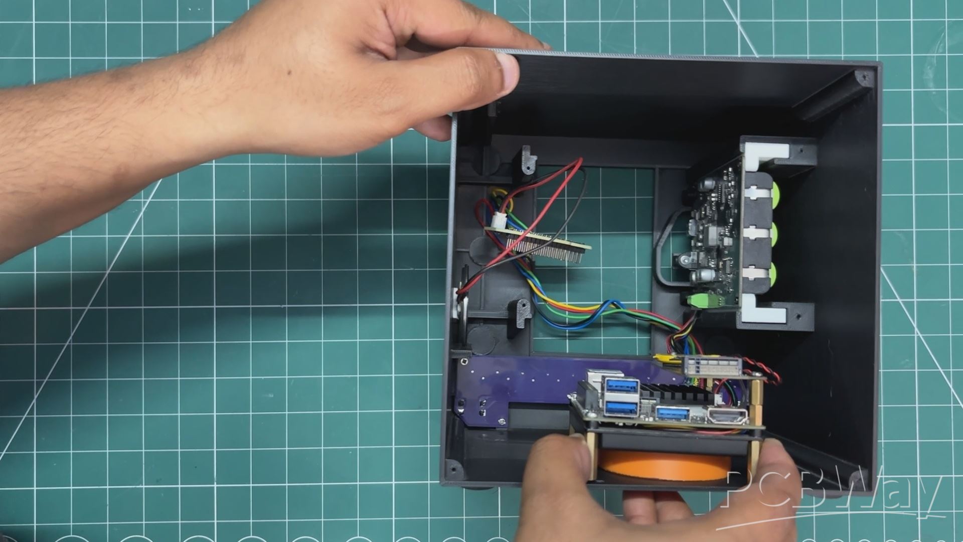
- The bottom grill part is first positioned in the opening of the main body.
- Then, we place the UPS board and the LattePanda inside the enclosure. The UPS board slides into position thanks to the holder parts attached to it.
- Using M2 PCB standoffs, the LattePanda is positioned above the grill and secured in place with four M2 bolts.
- After assembling both the LattePanda and the UPS board, we reconnect the breakout board to the GPIO headers, as it was removed earlier during the front I/O board assembly to make things easier.
AIR INTAKE FAN ASSEMBLY
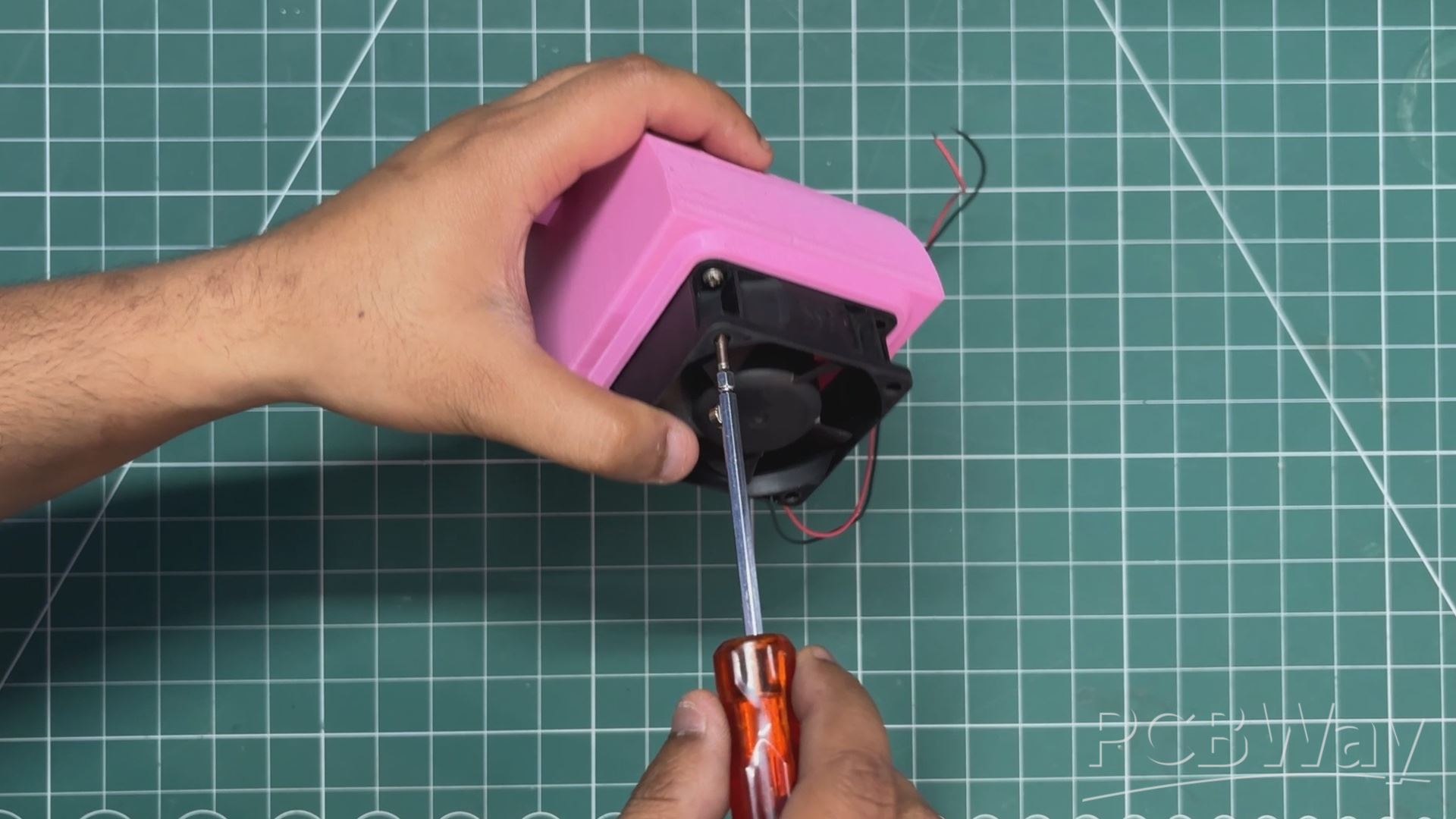
- The air intake fan assembly process begins by placing the PC fan in position over the air duct, then securing it with four M2 screws. We ensure that the airflow direction is set so that the fan blows air into the enclosure from the outside.
- The fan–air duct assembly is then positioned over the grill mesh on the lid and secured in place using two M2 screws.
- Next, we install a lever switch in the opening provided for it. We remove the nut from the switch, insert the switch through the opening from the inside, and then tighten the nut to secure it in place.
- The fan’s positive wire is connected to the common terminal of the lever switch. A red wire is connected to the NO (normally open) terminal, which serves as the fan’s positive line. This allows the lever switch to control the power to the fan.
- We then remove the UPS board from its mounting position and connect the positive and negative terminals of the fan to the battery output terminals of the UPS board. A CON2 screw terminal is used to secure these connections.
Now, when the UPS board is powered on, toggling the lever switch will turn the fan on and off.
POWER ADAPTOR BOARD & LID ASSEMBLY
- We begin the power adapter board assembly process by placing the mechanical switch into the slot on the power adapter board.
- Next, we insert the DC barrel jack into the hole on the power adapter board and secure it in place using a nut from the other side.
- We then attach red and black wires to the DC jack’s VCC and GND terminals. This is followed by connecting two single-core silver copper wires to the terminals of the mechanical switch. We solder these wires to the switch terminals on the LattePanda breakout board.
- The DC barrel jack is connected to the input of the UPS board. The idea here is to charge the UPS board whenever we plug power into the DC jack mounted on the back side of our Steam box.
- After completing all the wiring connections, we slide the power adapter board into position, align the mounting holes with those on the lid, and use two M2 screws to secure it in place.
LID & MAIN BODY ASSEMBLY
- The lid is placed in position on the back side of the main body; we simply push it in, and it locks into place.
- To secure it permanently, we use four M2 screws placed near each vertex, which firmly fasten the lid to the main body.
STEAM LOGO ASSEMBLY
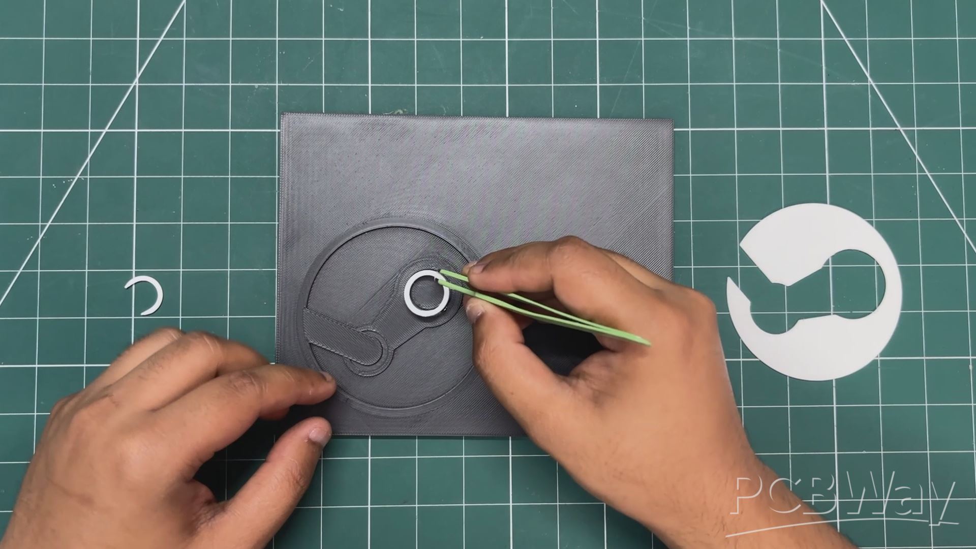
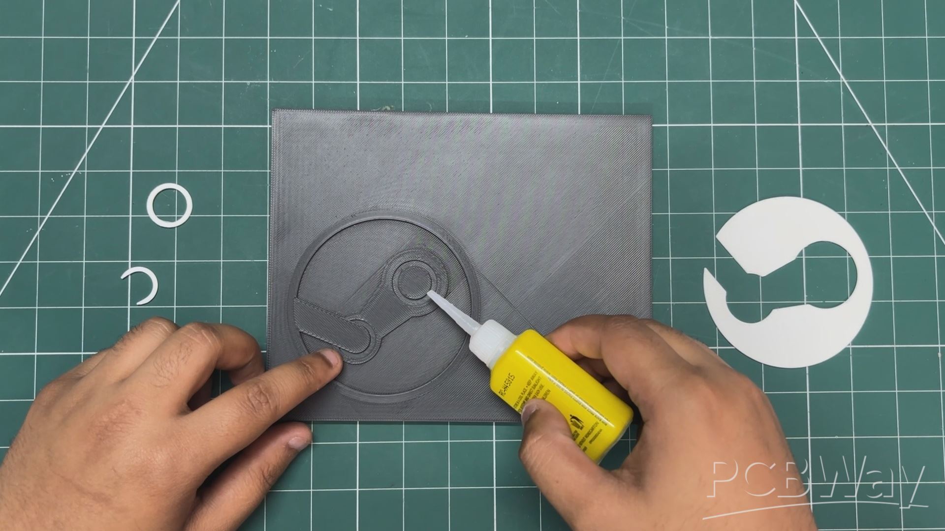
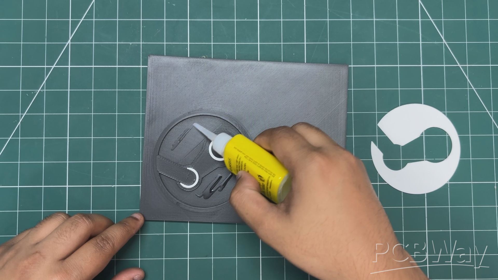
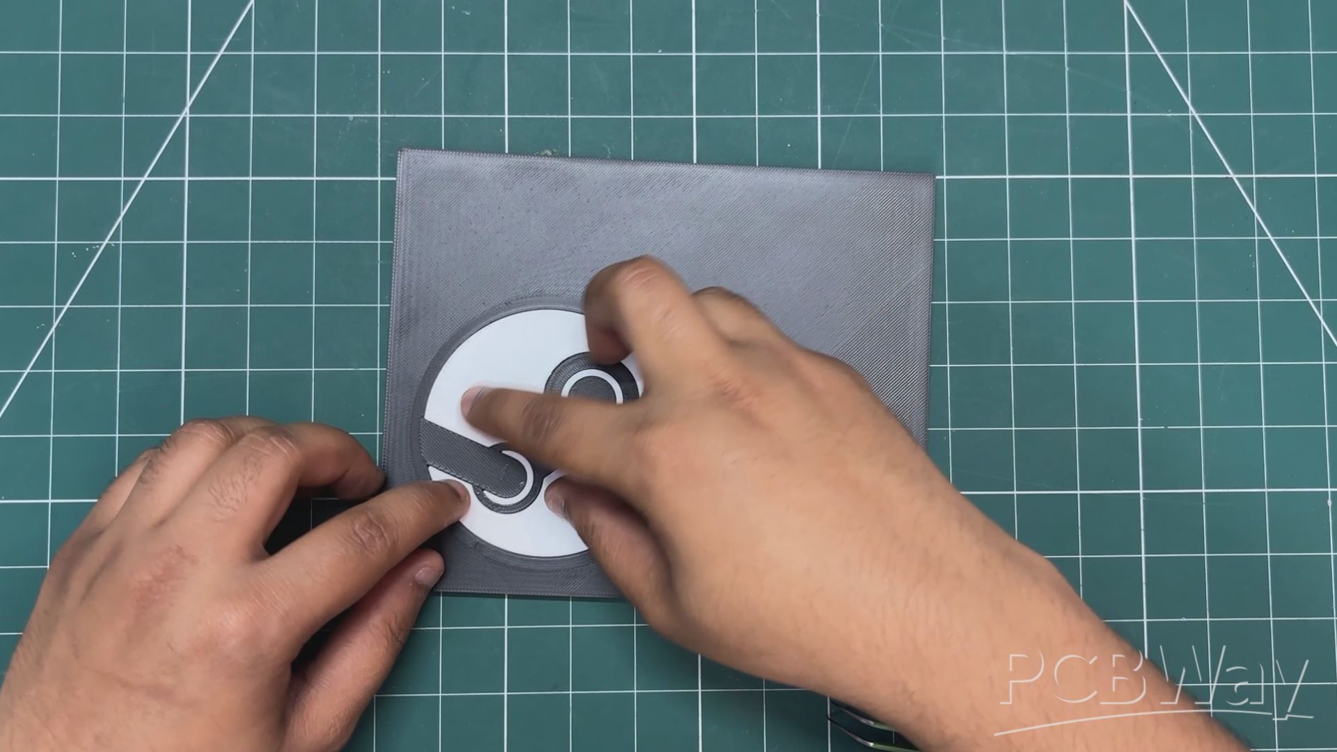
Next, we apply some super glue inside the Steam logo part, then place the white logo insert in position, followed by both rings.
After a few minutes, the glue hardens, securing everything in place.
MAGNET ASSEMBLY
Next comes the final assembly step: adding the magnets. The way magnets work is simple; we all know that north attracts south, while north repels north (and vice versa).
- We are using 5 mm diameter magnets, stacked together in a line. One by one, we place each magnet into the holes we modeled on the front side of the main body. There are six holes, so we add six magnets. We make sure to orient them so that the north side faces inward.
- Similarly, we add magnets to the holes on the inside of the front cover. This time, we ensure that the south side of each magnet faces inward, so the outer face is south.
By doing this, we can attach the front cover to the main body using magnetism alone.
This completes the assembly process.
RESULT
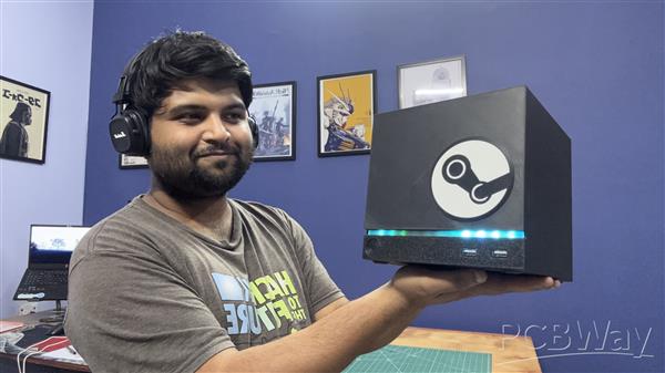
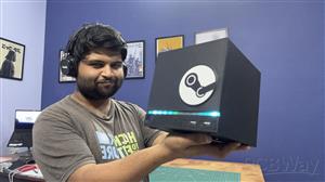
Here’s the final result of this tedious yet incredibly fun build: a fully functional Steam Machine. It may not be made by Valve, but built completely from scratch by me.
At its core is the LattePanda IOTA single-board computer, powered by an Intel N150 quad-core processor. For the operating system, I chose Bazzite, a KDE-based Linux distro designed specifically for gaming and running Steam.
The entire enclosure was designed from scratch in Fusion 360, taking inspiration from the latest Steam Machine design language. I even added a magnetic front cover, allowing it to be easily swapped with different designs. On the front, there’s a light bar similar to official Steam Machines, featuring 11 WS2812B RGB LEDs, with animations controlled via a push button.
The system is powered by a 12V 4A adapter, along with an integrated UPS module that enables internal battery-powered operation. For thermal management, I included an air intake fan to ensure proper airflow because, without ventilation, this compact box would quickly turn into a heat trap.
BENCHMARKS
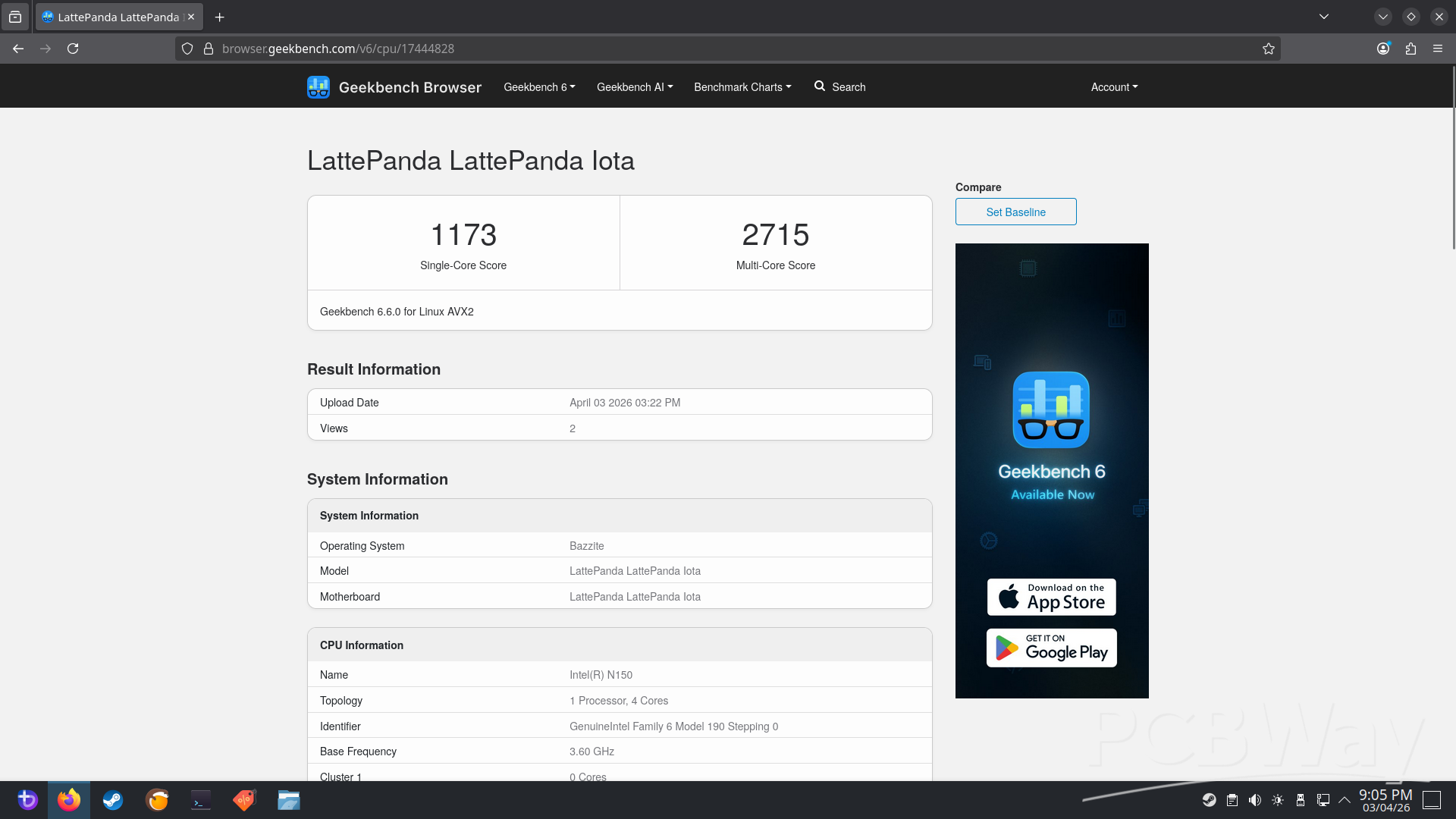
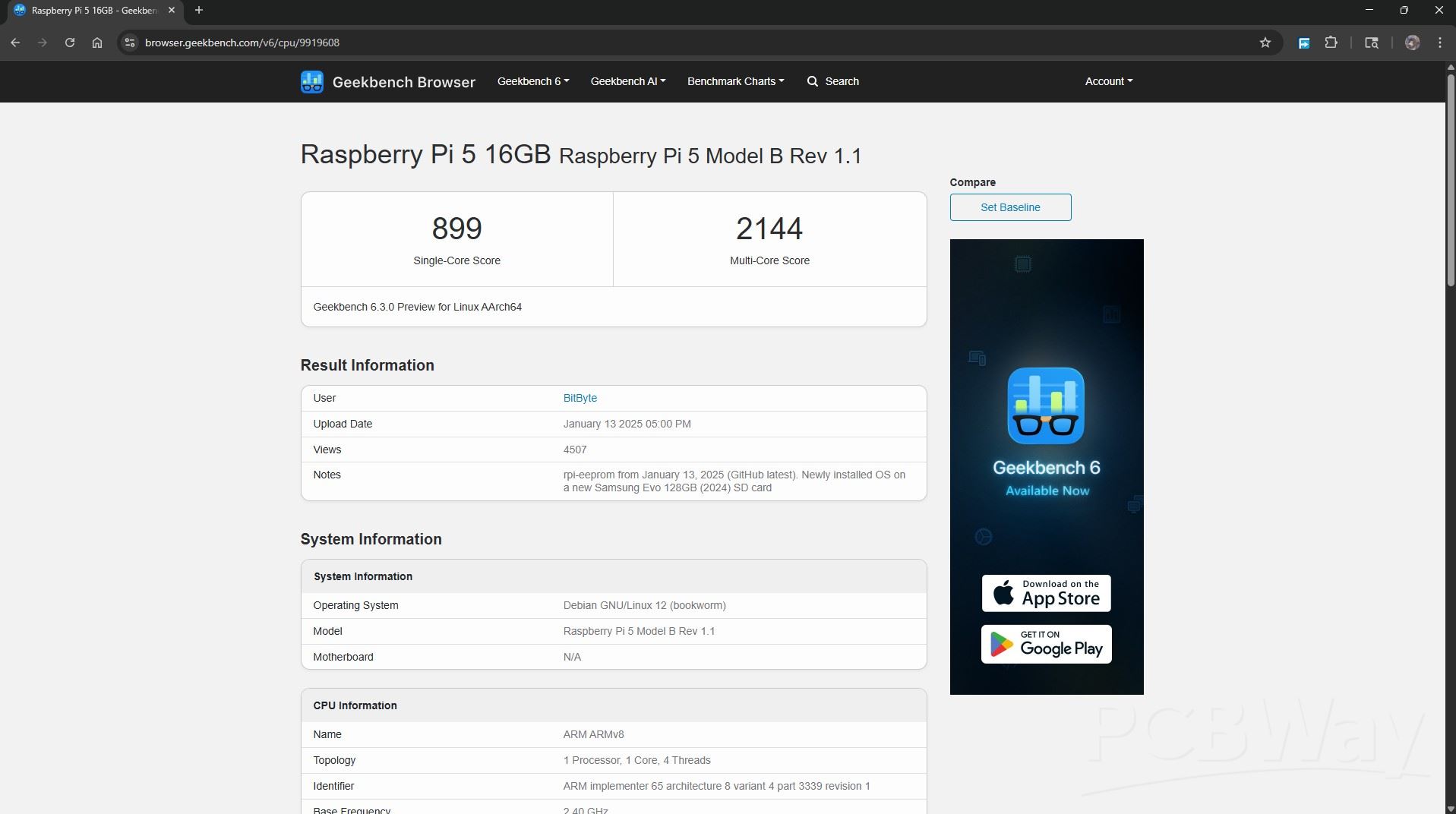
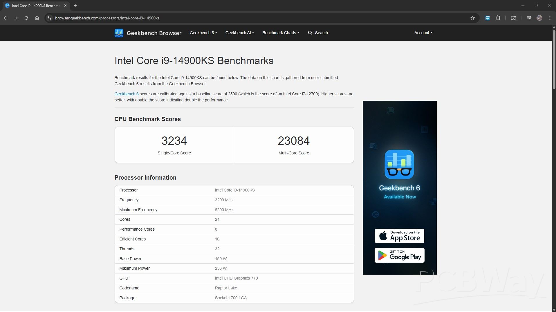
For testing, I ran Geekbench 6 on this setup and got a single-core score of 1173 and a multi-core score of 2715.
For comparison, a Raspberry Pi typically scores around 800–900 in single-core and about 2000–2200 in multi-core (for the 16GB variant). On the other end of the spectrum, something like an Intel i9-14900KS pulls in roughly 3000–3300 single-core and a massive 25,000+ in multi-core.
On paper, our Steam Machine isn’t exactly a powerhouse, but numbers are kinda boring anyway.
Let’s get to the real test: playing some games on it.
HALF LIFE 2
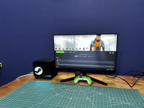
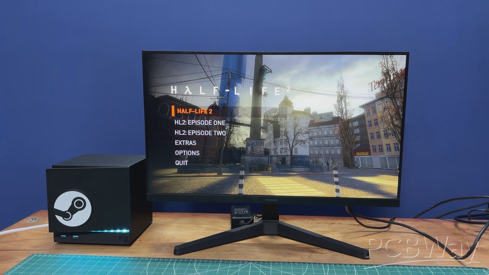
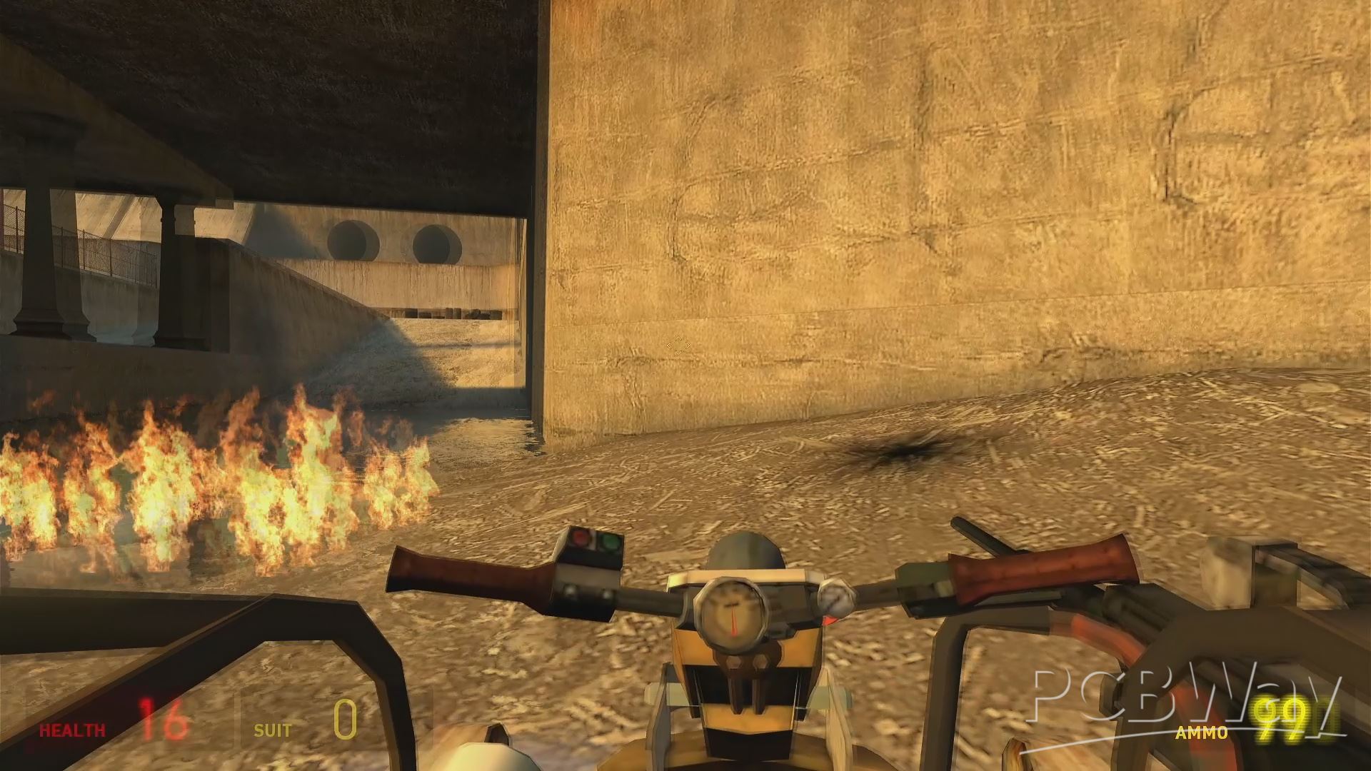
If you’re building a Steam Machine, it’s basically a crime not to run Half-Life on it — so of course, I did.
I tried Half-Life 2, and yeah, it ran great. Not surprising, considering Half-Life 2 is almost 20 years old at this point — but still, the experience was solid and honestly really enjoyable.
The only thing I don’t like is that we still don’t have Half-Life 3.
CLASSIC DOOM
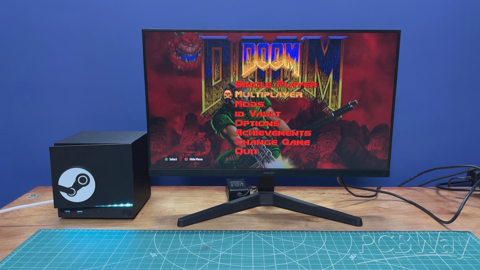
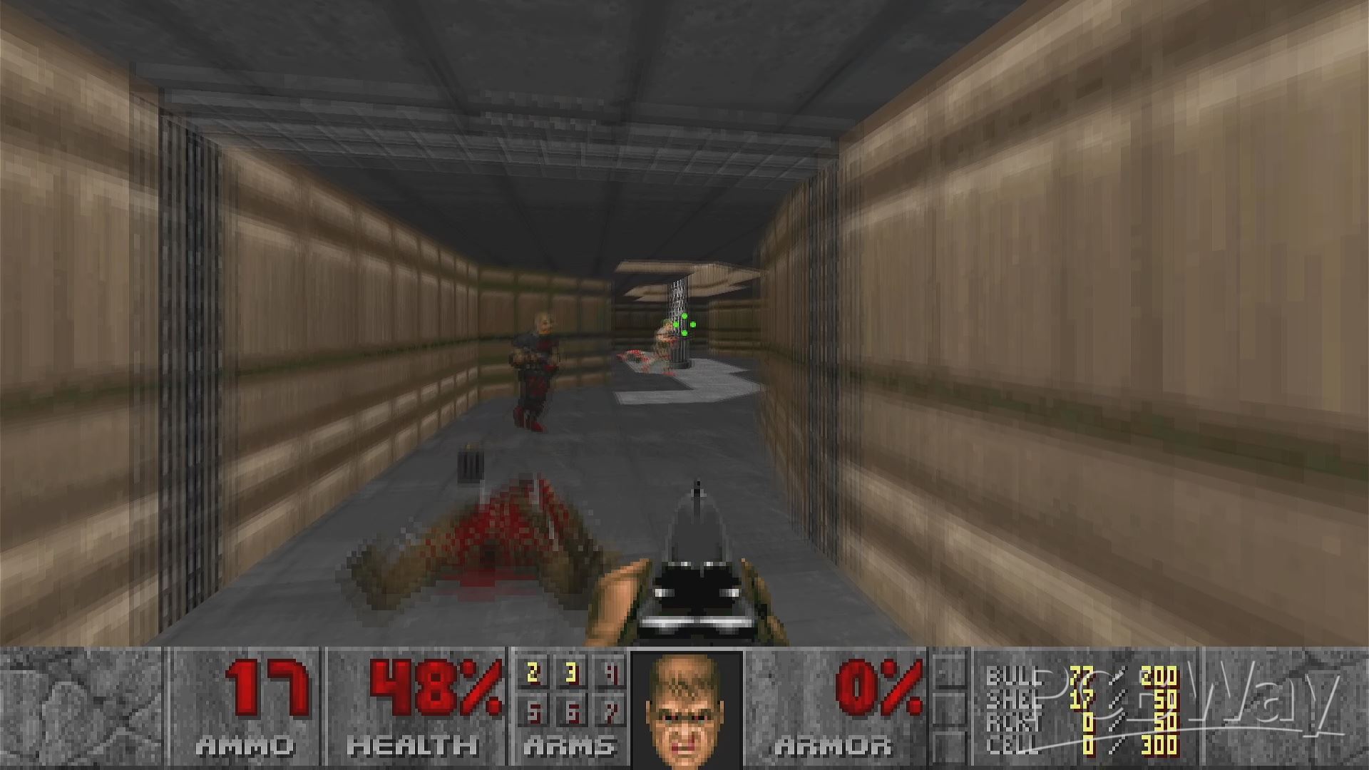
Next up was DOOM, and it ran buttery smooth, which is honestly not surprising.
At this point, DOOM has been run on everything from calculators to receipt printers.
heck, I even saw someone run it on E. coli cells, so this little Steam Machine barely even breaks a sweat.
FALLOUT NEW VEGAS
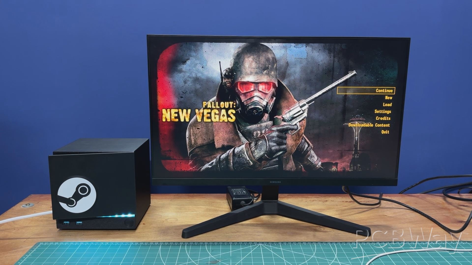

Next entry on my list was Fallout: New Vegas. It’s a pretty old title at this point, but honestly, it still has a far better story than Fallout 4.
I recently started playing it again, and I’m still discovering new quests and details here and there, which really shows how much work Obsidian put into this game.
As for performance, it runs more than playably on this setup. I genuinely don’t have anything negative to say—it just works.
NIER AUTOMATA
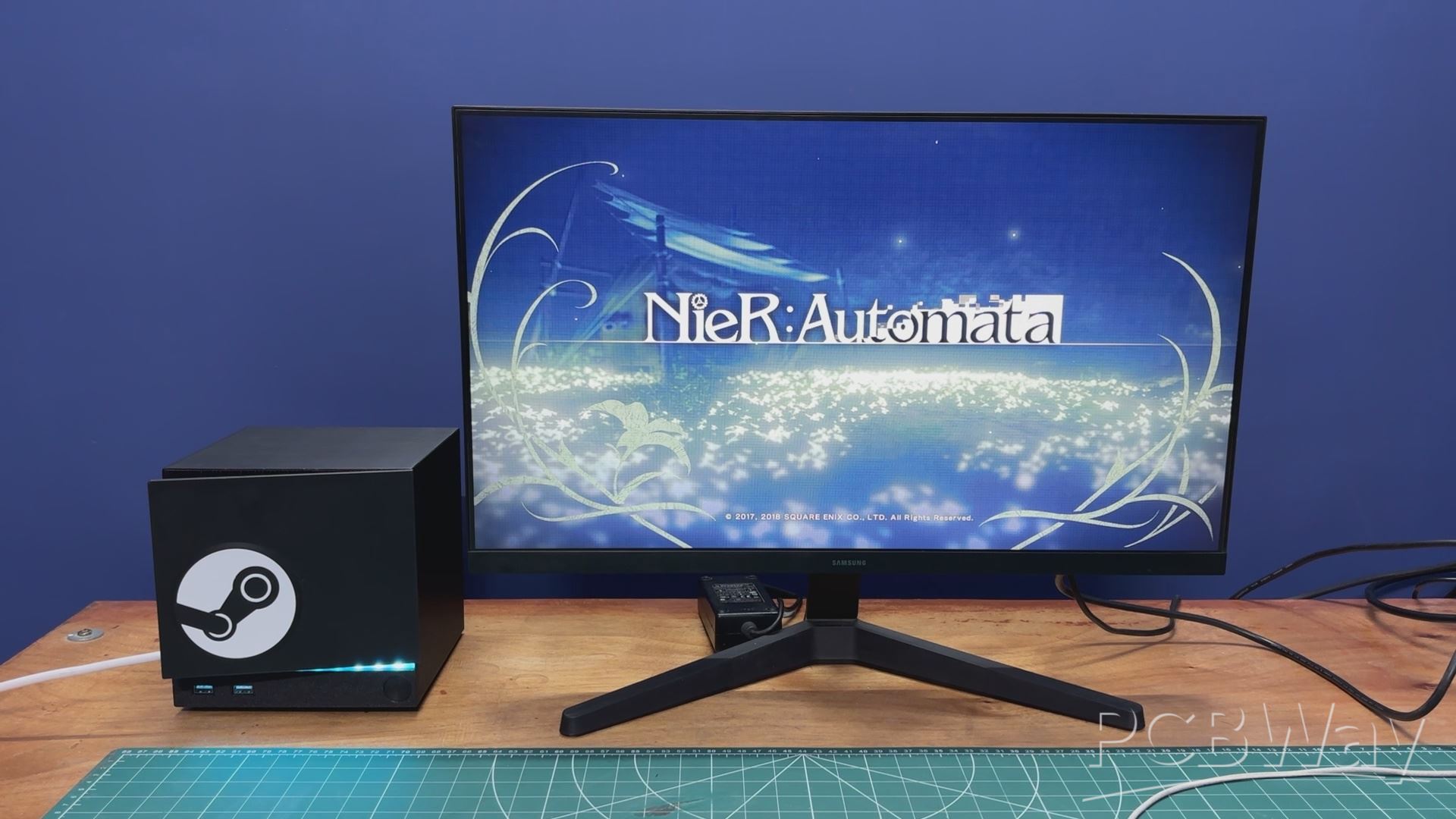
Next up was NieR: Automata. I absolutely love this game—especially its soundtrack.
Fun fact: they actually created a completely made-up language just for the songs, which makes it even more unique.
Performance-wise, it’s playable, but I did notice some strain. The game runs in the 30–40 FPS range. It’s a relatively modern and graphically demanding title, so that’s understandable—but hey, our potato Steam Machine still manages to handle it.
BAYONETTA
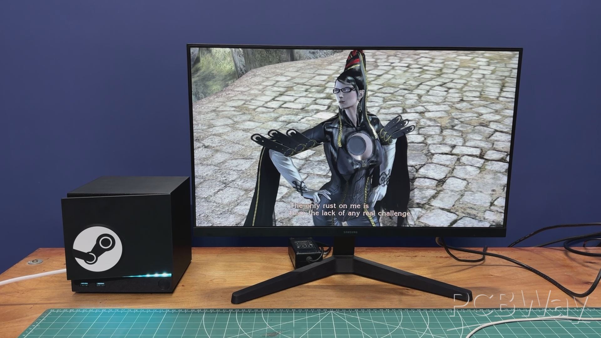
Next, I tested Bayonetta 1, and it ran exceptionally smoothly. Performance stayed consistently above 40 FPS, and the overall experience felt very close to running the game on a standard desktop PC. It really shows that this system can handle less demanding titles quite comfortably.
And honestly, Bayonetta is an absolute gem. It’s crazy good, and I have no idea why more people don’t talk about it.
HOLLOW KNIGHT: SILKSONG
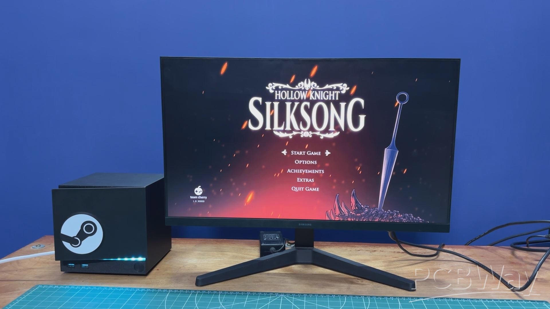
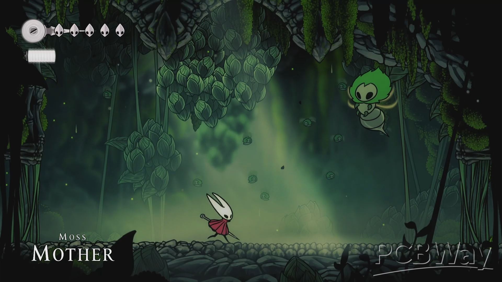
We also tested a popular indie title, Hollow Knight: Silksong, and it ran really well on this setup. That’s not too surprising, though. Silksong is a beautifully animated 2D game that relies more on art style and smooth animations than raw GPU power. Because of that, it plays perfectly to the strengths of the N150 and Intel integrated graphics, delivering smooth frame rates and responsive gameplay without heavily stressing the system. It’s a great example of how this setup shines with well-optimized indie games.
CONCLUSION
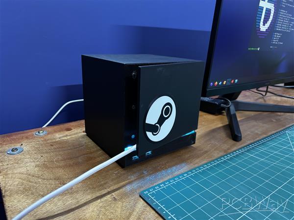
One thing I want to highlight is the really frustrating experience I had while trying to install the TP-Link Archer TX10U Nano. Drivers for it were not available for Bazzite. I did try to install them, but it failed, so I had to use an Ethernet cable instead.
I simply had to remove the front cover of the Steam Machine and connect the cable to the Ethernet port. With the magnetic cover attached back in place, it does look a bit odd, but you gotta do what you gotta do.
If anyone wants to try this, I’d recommend getting an Intel AX201NGW Wi-Fi card instead; its drivers are readily available and will save you a lot of headaches.
Most of the things I ran on this little machine worked quite well, considering this is all running on a single-board computer. The IOTA isn’t meant to be a gaming device, as it lacks one of the most important components for gaming, which is a dedicated GPU, or even a powerful integrated GPU.
I also have a ROG Ally, whose motherboard is similar in size to the IOTA, but it features an AMD Z1 Extreme with RDNA3 graphics. That’s a proper handheld console chip, and maybe in the future we’ll see similar hardware in the single-board computer space. There are already a few SBCs with AMD chips, but that’s going a bit off topic. My point is that this setup works well with most older games and even some newer ones.
One thing I’d like to do in version 2 of this project, if I decide to make one, is to swap out this SBC for something that includes a PCIe x16 slot. That would allow me to add a desktop-class GPU, or at least use a much more powerful SBC.
For now, this project is complete, and all the details related to it are available in the article. Let me know what you think of this project in the comments, and I’ll be back with a new project very soon.
Peace out!
#include <Adafruit_NeoPixel.h>
#define LED_PIN 1
#define BTN_PIN 0
#define NUM_LEDS 11
#define BRIGHTNESS 80
Adafruit_NeoPixel strip(NUM_LEDS, LED_PIN, NEO_GRB + NEO_KHZ800);
int mode = 0;
const int TOTAL_MODES = 7;
int lastBtnState = HIGH;
unsigned long lastDebounce = 0;
const unsigned long DEBOUNCE_MS = 50;
uint32_t TEAL = strip.Color(0, 200, 180);
uint32_t RED_COLOR = strip.Color(180, 0, 0);
unsigned long lastUpdate = 0;
int animStep = 0;
float breathVal = 0.0;
float breathDir = 1.0;
void setup() {
strip.begin();
strip.setBrightness(BRIGHTNESS);
strip.show();
pinMode(BTN_PIN, INPUT_PULLUP);
}
void loop() {
handleButton();
runAnimation();
}
void handleButton() {
int reading = digitalRead(BTN_PIN);
if (reading != lastBtnState) lastDebounce = millis();
if ((millis() - lastDebounce) > DEBOUNCE_MS) {
if (reading == LOW) {
mode = (mode + 1) % TOTAL_MODES;
animStep = 0;
breathVal = 0.0;
breathDir = 1.0;
strip.clear();
strip.show();
delay(200);
}
}
lastBtnState = reading;
}
void runAnimation() {
switch (mode) {
case 0: modeSteadyTeal(); break;
case 1: modeChase(); break;
case 2: modeBreathingTeal(); break;
case 3: modeComet(); break;
case 4: modeRainbowFlow(); break;
case 5: modeSolidRed(); break;
case 6: modeRedPulse(); break;
}
}
void modeSteadyTeal() {
if (millis() - lastUpdate < 500) return;
lastUpdate = millis();
for (int i = 0; i < NUM_LEDS; i++) strip.setPixelColor(i, TEAL);
strip.show();
}
void modeChase() {
if (millis() - lastUpdate < 60) return;
lastUpdate = millis();
strip.clear();
strip.setPixelColor(animStep % NUM_LEDS, TEAL);
strip.show();
animStep++;
}
void modeBreathingTeal() {
if (millis() - lastUpdate < 20) return;
lastUpdate = millis();
breathVal += breathDir * 2.0;
if (breathVal >= 255) { breathVal = 255; breathDir = -1; }
if (breathVal <= 0) { breathVal = 0; breathDir = 1; }
float f = breathVal / 255.0;
uint32_t c = strip.Color(0, (int)(200 * f), (int)(180 * f));
for (int i = 0; i < NUM_LEDS; i++) strip.setPixelColor(i, c);
strip.show();
}
void modeComet() {
if (millis() - lastUpdate < 50) return;
lastUpdate = millis();
for (int i = 0; i < NUM_LEDS; i++) {
uint32_t c = strip.getPixelColor(i);
uint8_t r = ((c >> 16) & 0xFF) * 0.5;
uint8_t g = ((c >> 8) & 0xFF) * 0.5;
uint8_t b = ( c & 0xFF) * 0.5;
strip.setPixelColor(i, strip.Color(r, g, b));
}
strip.setPixelColor(animStep % NUM_LEDS, TEAL);
strip.show();
animStep++;
}
void modeRainbowFlow() {
if (millis() - lastUpdate < 30) return;
lastUpdate = millis();
for (int i = 0; i < NUM_LEDS; i++) {
int hue = ((animStep * 3 + i * (65536 / NUM_LEDS)) & 0xFFFF);
strip.setPixelColor(i, strip.gamma32(strip.ColorHSV(hue, 255, 200)));
}
strip.show();
animStep++;
}
void modeSolidRed() {
if (millis() - lastUpdate < 500) return;
lastUpdate = millis();
for (int i = 0; i < NUM_LEDS; i++) strip.setPixelColor(i, RED_COLOR);
strip.show();
}
void modeRedPulse() {
if (millis() - lastUpdate < 20) return;
lastUpdate = millis();
breathVal += breathDir * 2.0;
if (breathVal >= 255) { breathVal = 255; breathDir = -1; }
if (breathVal <= 0) { breathVal = 0; breathDir = 1; }
float f = breathVal / 255.0;
uint32_t c = strip.Color((int)(180 * f), 0, 0);
for (int i = 0; i < NUM_LEDS; i++) strip.setPixelColor(i, c);
strip.show();
}

STEAM MACHINE Iota
*Wpsload community is a sharing platform. We are not responsible for any design issues and parameter issues (board thickness, surface finish, etc.) you choose.


Attribution-ShareAlike (CC BY-SA) License
Read More⇒


Raspberry Pi 5 7 Inch Touch Screen IPS 1024x600 HD LCD HDMI-compatible Display for RPI 4B 3B+ OPI 5 AIDA64 PC Secondary Screen(Without Speaker)
BUY NOW


- Comments(1)
- Likes(6)
More by Arnov Arnov sharma
-
 DIY XBOX Controller
Greetings everyone, and welcome back. Here's something fun and custom.This is my version of an Xbox ...
DIY XBOX Controller
Greetings everyone, and welcome back. Here's something fun and custom.This is my version of an Xbox ...
-
 Pocket SNES
Greetings everyone, and welcome back! Today, I’ve got something fun and tiny to share—the Pocket SNE...
Pocket SNES
Greetings everyone, and welcome back! Today, I’ve got something fun and tiny to share—the Pocket SNE...
-
 Batocera Arcade Box
Greetings everyone and welcome back, Here's something. Fun and nostalgic. Right now, we are using ou...
Batocera Arcade Box
Greetings everyone and welcome back, Here's something. Fun and nostalgic. Right now, we are using ou...
-
 64x32 Matrix Panel Setup with PICO 2
Greetings everyone and welcome back.So here's something fun and useful: a Raspberry Pi Pico 2-powere...
64x32 Matrix Panel Setup with PICO 2
Greetings everyone and welcome back.So here's something fun and useful: a Raspberry Pi Pico 2-powere...
-
 Portable Air Quality Meter
Hello everyone, and welcome back! Today, I have something incredibly useful for you—a Portable Air Q...
Portable Air Quality Meter
Hello everyone, and welcome back! Today, I have something incredibly useful for you—a Portable Air Q...
-
 WALKPi PCB Version
Greetings everyone and welcome back, This is the WalkPi, a homebrew audio player that plays music fr...
WALKPi PCB Version
Greetings everyone and welcome back, This is the WalkPi, a homebrew audio player that plays music fr...
-
 Delete Button XL
Greetings everyone and welcome back, and here's something fun and useful.In essence, the Delete Butt...
Delete Button XL
Greetings everyone and welcome back, and here's something fun and useful.In essence, the Delete Butt...
-
 Arduino Retro Game Controller
Greetings everyone and welcome back. Here's something fun.The Arduino Retro Game Controller was buil...
Arduino Retro Game Controller
Greetings everyone and welcome back. Here's something fun.The Arduino Retro Game Controller was buil...
-
 Super Power Buck Converter
Greetings everyone and welcome back!Here's something powerful, The SUPER POWER BUCK CONVERTER BOARD ...
Super Power Buck Converter
Greetings everyone and welcome back!Here's something powerful, The SUPER POWER BUCK CONVERTER BOARD ...
-
 Pocket Temp Meter
Greetings and welcome back.So here's something portable and useful: the Pocket TEMP Meter project.As...
Pocket Temp Meter
Greetings and welcome back.So here's something portable and useful: the Pocket TEMP Meter project.As...
-
 Pico Powered DC Fan Driver
Hello everyone and welcome back.So here's something cool: a 5V to 12V DC motor driver based around a...
Pico Powered DC Fan Driver
Hello everyone and welcome back.So here's something cool: a 5V to 12V DC motor driver based around a...
-
 Mini Solar Light Project with a Twist
Greetings.This is the Cube Light, a Small and compact cube-shaped emergency solar light that boasts ...
Mini Solar Light Project with a Twist
Greetings.This is the Cube Light, a Small and compact cube-shaped emergency solar light that boasts ...
-
 PALPi V5 Handheld Retro Game Console
Hey, Guys what's up?So this is PALPi which is a Raspberry Pi Zero W Based Handheld Retro Game Consol...
PALPi V5 Handheld Retro Game Console
Hey, Guys what's up?So this is PALPi which is a Raspberry Pi Zero W Based Handheld Retro Game Consol...
-
 DIY Thermometer with TTGO T Display and DS18B20
Greetings.So this is the DIY Thermometer made entirely from scratch using a TTGO T display board and...
DIY Thermometer with TTGO T Display and DS18B20
Greetings.So this is the DIY Thermometer made entirely from scratch using a TTGO T display board and...
-
 Motion Trigger Circuit with and without Microcontroller
GreetingsHere's a tutorial on how to use an HC-SR505 PIR Module with and without a microcontroller t...
Motion Trigger Circuit with and without Microcontroller
GreetingsHere's a tutorial on how to use an HC-SR505 PIR Module with and without a microcontroller t...
-
 Motor Driver Board Atmega328PU and HC01
Hey, what's up folks here's something super cool and useful if you're making a basic Robot Setup, A ...
Motor Driver Board Atmega328PU and HC01
Hey, what's up folks here's something super cool and useful if you're making a basic Robot Setup, A ...
-
 Power Block
Hey Everyone what's up!So this is Power block, a DIY UPS that can be used to power a bunch of 5V Ope...
Power Block
Hey Everyone what's up!So this is Power block, a DIY UPS that can be used to power a bunch of 5V Ope...
-
 Goku PCB Badge V2
Hey everyone what's up!So here's something SUPER cool, A PCB Board themed after Goku from Dragon Bal...
Goku PCB Badge V2
Hey everyone what's up!So here's something SUPER cool, A PCB Board themed after Goku from Dragon Bal...
-
-
ARPS-2 – Arduino-Compatible Robot Project Shield for Arduino UNO
2532 0 5 -
A Compact Charging Breakout Board For Waveshare ESP32-C3
2987 3 8 -
AI-driven LoRa & LLM-enabled Kiosk & Food Delivery System
3195 2 1 -
-
-
-
ESP32-C3 BLE Keyboard - Battery Powered with USB-C Charging
3262 0 2


